Bulk case feeder for wire jumpers.pdf - 第13页
Special Design 2 Assembly instruct ions Special design for bulk case feeder for wire jumper s (00166278-01) 04/2007 Edition 13 2.2 Safety instructions WA R N I N G The safety instructions from the “Operational safe ty” c…
2 Assembly instructions Special design for bulk case feeder for wire jumpers (00166278-01) Special Design
04/2007 Edition
12
2
2
The feeder activation circuit provides the cycle time between pick-up operations that is set in
SIPLACE Pro. 2
A knurled screw which is secured with a grub screw is used to set the vibration intensity. This set-
ting always applies to both tracks. 2
The component container must always be filled with at least 6000 components. 2
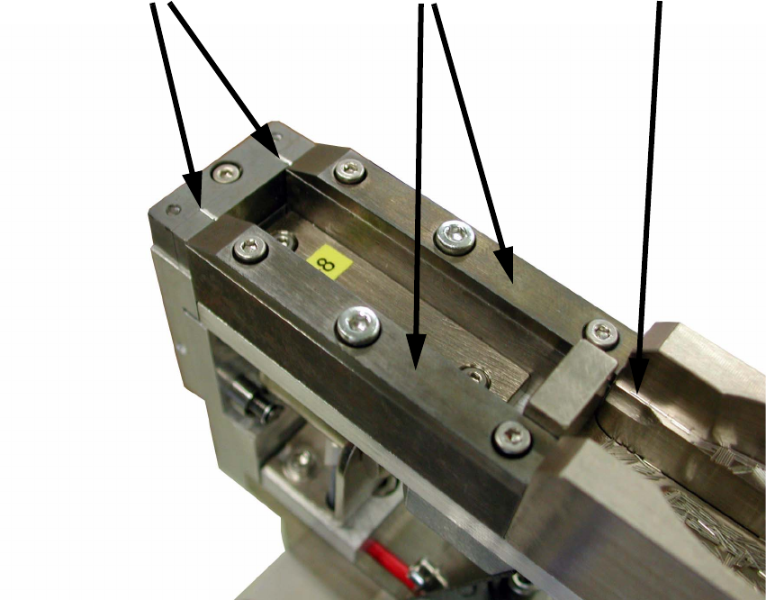
The components are separated via a series of chicanes through to the infeed to the feeding rails.
The pressure of the following components pushes the components into the pick-up position. To
prevent the components becoming caught up on any burrs, the pick-up position is separated via
a lifting magnet 1/10 mm before pick-up. This stroke is adjustable, but a larger separation is not
recommended. 2
2
Feeding rail cover
Separation
Pick-up positions

Special Design 2 Assembly instructions Special design for bulk case feeder for wire jumpers (00166278-01)
04/2007 Edition
13
2.2 Safety instructions
WARNING
The safety instructions from the “Operational safety” chapter of the user manual and servicing in-
structions take precedence over these instructions. 2
The SIPLACE placement machines are supplied with main power voltage.
Consequently parts of these systems carry dangerous voltages! This voltage is present at certain
modules inside the machine base, even when the machine is switched off at the main power
switch.
Incorrect handling of the placement machine or touching live parts of the machine can result in
death or severe injury, and considerable damage to equipment.
BEFORE starting any work, shut down the operating system correctly, then switch the machine
OFF at the main power switch and disconnect from the mains power supply. In addition, the com-
pressed air supply must be switched off at the compressed air unit's main valve in the machine
base and vented by actuating the needle valve on the compressed air unit.
There is DANGER for heart pacemaker wearers in the vicinity of the linear motors, as described
in detail in the "Special safety instructions for working in the vicinity of strong magnetic fields"
section of the user manual and service manual.
Always follow the accident prevention regulations, DIN or other standards and special safety
rules applicable in your country.
Pay attention to the information concerning residual voltages in the Operational Safety chapter.
Follow the ESD regulations as described in the operational safety section of the operating
instructions.
During the assembly, always secure the machine to prevent access by other people and to pre-
vent it being switched on again. The procedure is described in the “Locking the machine…” sec-
tion of the user manual.
Working with the SITEST program further increases the risk of accident.
The SITEST program must only be used by authorized and trained personnel.
2
2 Assembly instructions Special design for bulk case feeder for wire jumpers (00166278-01) Special Design
04/2007 Edition
14
2.3 Requirements for fault-free operation
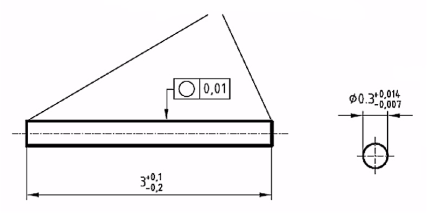
The components must conform to the specification. 2
2
Fig. 2.10 - 1 Dimensions of the wire segment
2
2
If the components are outside the tolerance, this will increase the number of feeder faults. 2
For fault-free operation, the components should be demagnetized. 2
A cycle time of 500 ms should be set and nozzle 902 assigned in SIPLACE Pro. 2
2
On the end faces, burring within the circular areas of
Ø 0.35 is permitted.