ASM_Nozzles_EN.pdf - 第6页
1 - 2 www.asm-smt.com Job Guide Structure This Job Guide is divided into separate chapters that deal with various different component groups. The first column on each page, "Components", shows the component sha…
1 - 1
www.asm-smt.com
1 - Introduction: General Information about Components, Nozzles and
Adapters
1 - 2
www.asm-smt.com
Job Guide Structure
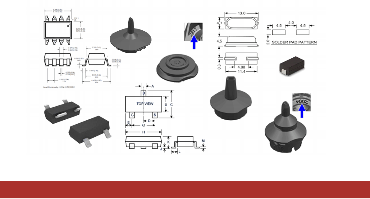
This Job Guide is divided into separate chapters that deal with various different component groups. The first column on
each page, "Components", shows the component shape details for the individual components and the name of the
corresponding GF file.
Simply search for the component to be placed (or the component shape), to find out which is the appropriate nozzle.
NOTICE
The component shape file names correspond to the original file names from the GF Editor of the programming
system.
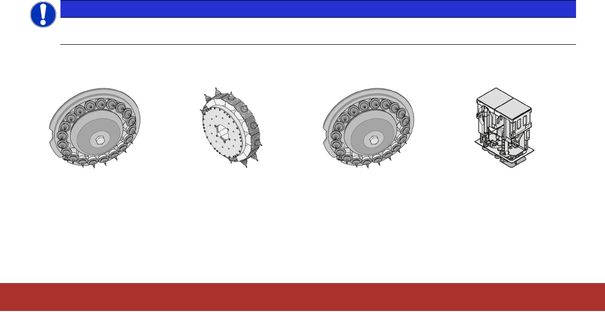
The four main columns Placement head C&P20A/M, CPP (internal and external camera), C&P20P/M2/P2 and
TwinHead show the nozzles to be used with the component shape(s) for each of the placement heads.
C&P20A/M
Collect & Place
20 segment
CPP
Collect & Place
(Internal or external camera)
C&P20P/M2/P2
Collect & Place
20 segment
Twin Head
1 - 3
www.asm-smt.com
NOTICE
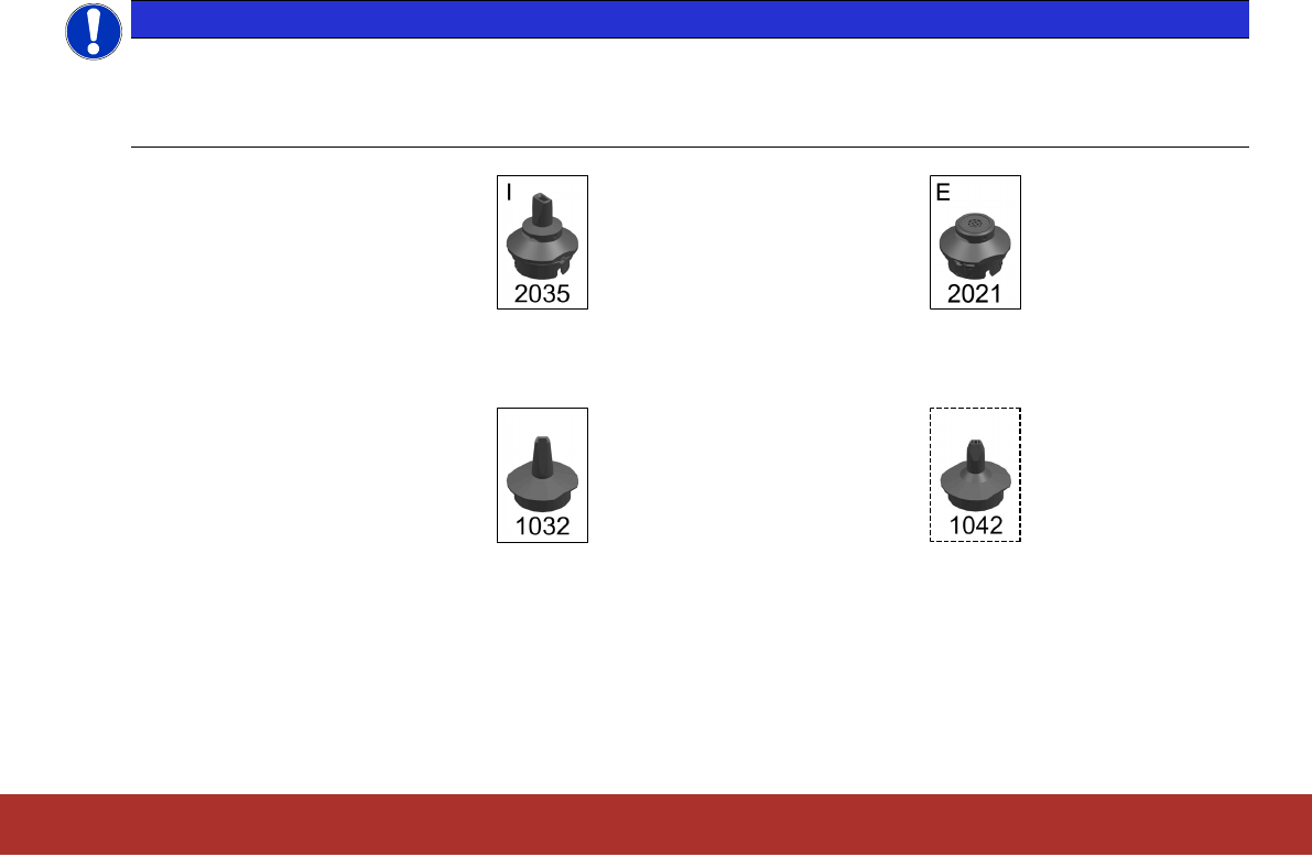
When using the SIPLACE CPP, components can either be centered with the internal head camera or with an
external stationary camera (P&P mode). Centering with the internal head camera uses the camera type SST30
for components up to 27mmx27mm. The external stationary camera type SST33 is used for components up
to a size of 50mmx40mm.
Example of internal camera: Example of external camera:
For some nozzles you can use alternative nozzles. These are marked with a dashed frame.
Example standard nozzle: Example alternative nozzle: