XPF-L 服务工程师训练手册中文版.pdf - 第144页
13.18 调整 tray 高度检查 sensor ( 在 tray tower 里面 ) 1. 选择 [Maintenance C] – [Custom Maintenance] ,进入到 maintenance 方式 . 2. 将 tray pallet master jig 装到 slot [01, 02] , and 并移动到 “Slot 01, 02 Supply” 位置 3. 将 two of the three-step …
13.16 调整 the tray catcher 原点位置的检查sensor
1. 选择 [Settings and management] – [Edit point table]到显示edit point table
画面。
2. 从servo 轴中,选择U轴,记录“Back”的数值。
3. 移动U轴的servo 数到“Back”的位置。
4. 找到sensor刚好ON的位置。
I/O: RX030 MTU_ShuttleRetChk
5. 在ON的方向,将sensor再移多0.5MM,并锁紧此sensor.
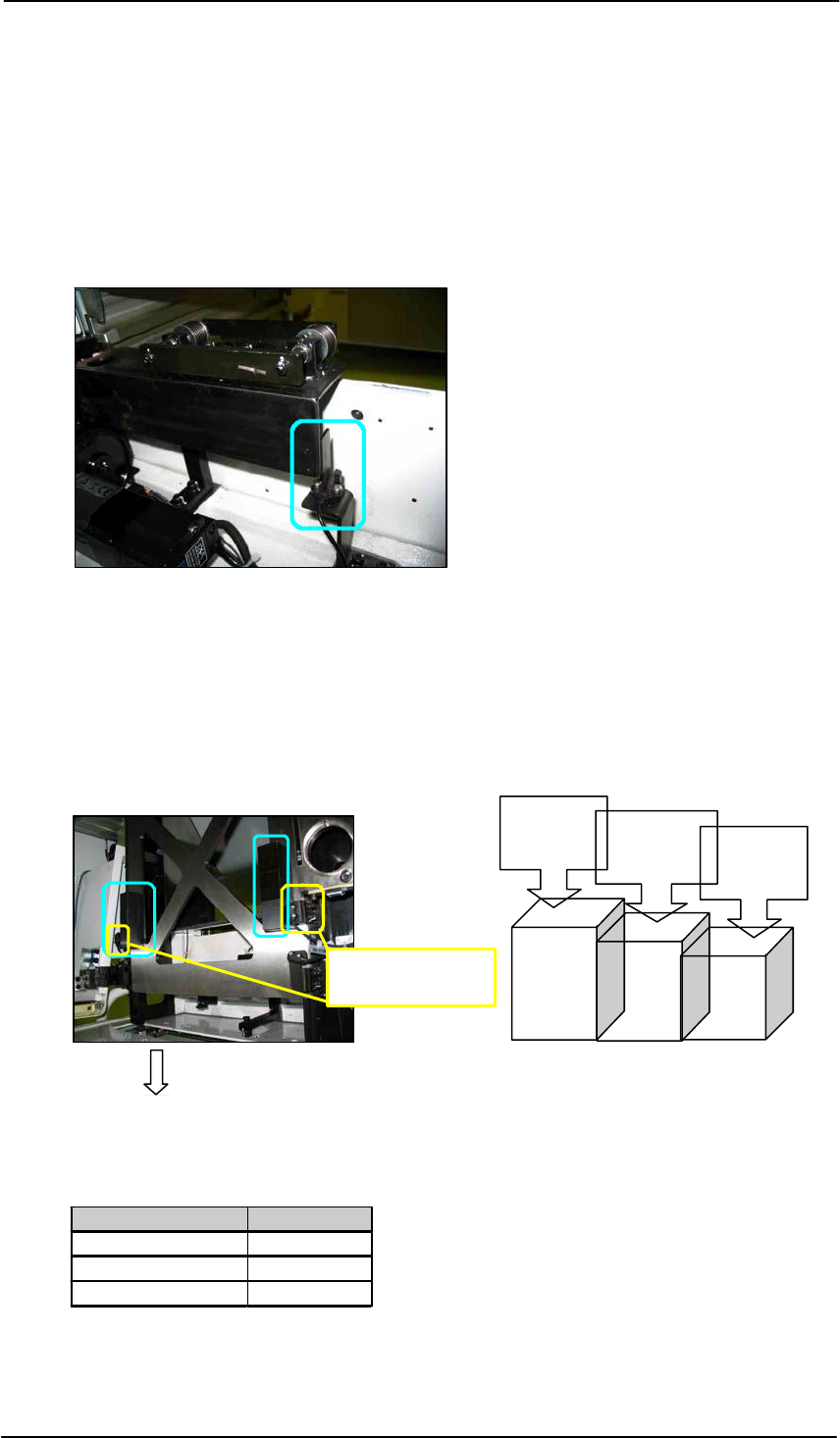
13.17 调整shuttle interlock sensor
1. 将 tray pallet master jig 装在U轴的运送带上。
2. 将 two of the three-step jigs 放在 tray pallet master jig上,使其对准interlock sensor, 如下图所
示。
Height
ブロックジグ( Z9631DEPJ3750)
Shuttle interlock
sensor
33.5 mm
1
Height
33.25 mm Height
33.0 mm
2 3
Tray tower side
Three step jig Z9631DEPJ3750
3. 调整发射和接受sensor的高度, 当step 1 jig对准时,使 [X018 TrayPaleHeightChk]
OFF 当step3 sensor对准时,使 [X018 TrayPaleHeightChk] ON.
Jig combination I/O Status
Step 1 + Step 1 OFF
Step 1 + Step 3 OFF
Step 3 + Step 3 ON
128
Fuji Machine Mfg. Co., Ltd
FK-9F98-55-0E
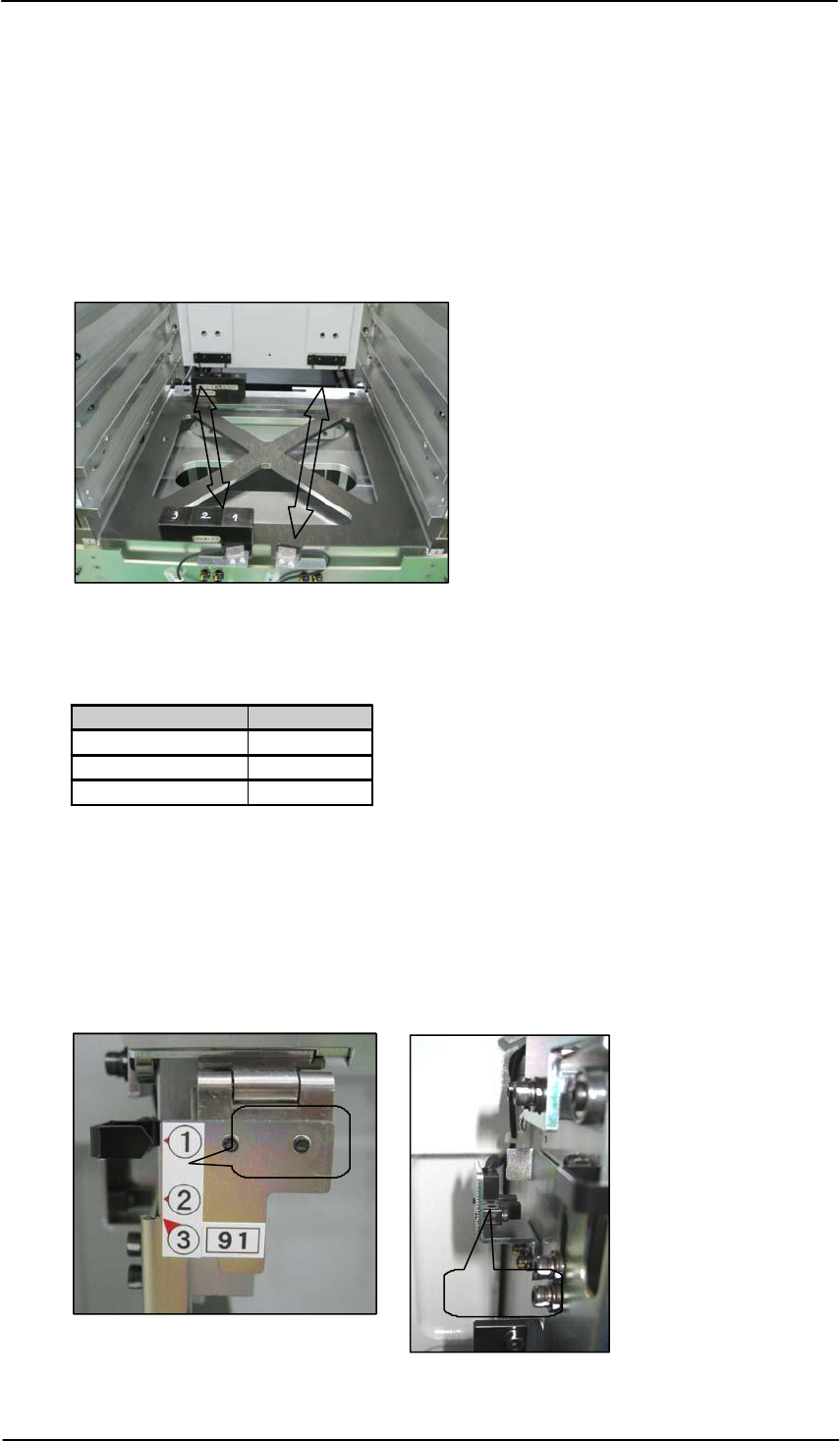
13.18 调整tray 高度检查sensor (在 tray tower里面)
1. 选择[Maintenance C] – [Custom Maintenance] ,进入到 maintenance方式.
2. 将 tray pallet master jig装到slot [01, 02] ,and并移动到 “Slot 01, 02 Supply”
位置
3. 将two of the three-step jigs 放在 tray pallet master jig 上,使其对准发射和接受sensor,
如下图所示。
4. 调整发射和接受sensor的高度,当step3 jig 对准时,[RX036 MTU_PalletAdvHeightChk2],
为ON。当step1 jig 对准时,[RX036 MTU_PalletAdvHeightChk2] 为OFF。
Jig combination I/O Status
Step 1 + Step 1 OFF
Step 1 + Step 3 OFF
Step 3 + Step 3 ON
5.用同样的方法调整右手边的 [RX035 MTU_PalletAdvHeightChk1 ] sensor.
13.19 调整 tray shutter检查 sensor
1. 调整sensor座的位置,当tray shutter 在position 1时,sensor 灯为OFF,升高shuttle 1MM
时,sensor 灯为ON 。
Tray
Shutter
Sensor
I/O: RX03A MTU_RrShutCloseChk
FK-9F98-55-0E
Fuji Machine Mfg. Co., Ltd
129
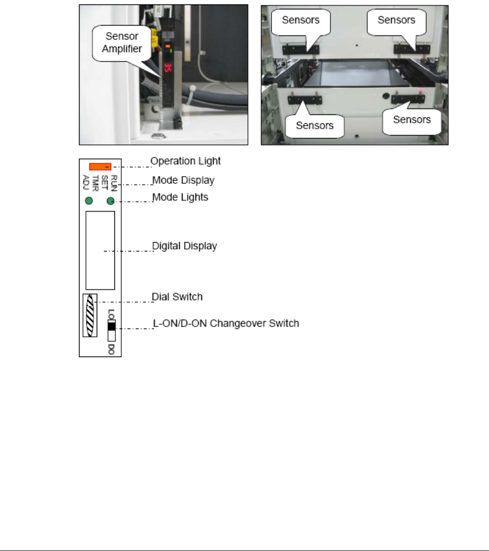
13.20 调整tray pallet 干扰 sensor
1. 将 the changeover switch 设为 L-ON.
2. 再按下 the dial switch ,(此时, 在 mode 显示内的 RUN 灯开始闪动,在 digital 显示上出现 AA )
3. 转动 dial switch,使 mode display RUN 变到 SET.
4. 持续按 e dial switch 到 3 秒以上(在 digital 显示 HP ,并 mode 灯开始 ON)
5. 再按 dial switch 一次, (到在 mode 显示为“SET”开始闪动,且在 digital display 显示 2P ).
6. 再按 dial switch 一次(2P 闪动).
7. 转动 dial switch 到 数字(0~100) 显示, 并 mode 灯变 ON.
8. 检查所显数字大于 3.
9. 转动 dial switch 到 2P 闪动.
10. 请确定 sensor 不被遮住,接着再按 dial switch 一次(在 2P 闪动中为 2)
130 Fuji Machine Mfg. Co., Ltd FK-9F98-55-0E