Spec of AX-3 AX-5 June 2005 LR.pdf - 第14页
Camera field of view Vision alignment Component size > 2.0 x 1.25 mm 2 (0805 passives) to 45mm x 45mm (1.77” x 1.77”) Min. Lead width 0.200mm (0.005”) Min. Lead pitch 0.400mm (0.012”) Min. Bump size 0.300mm (0.012”) 0…
2.7 Component
alignment
2.7.1 Component
laser
2.7.2 Vision
alignment
Figure 5
Figure 6
Contents
11 of 34
Components up to 45 x 45mm can be aligned with a component vision camera that
optionally can be fitted behind the board transport and underneath a standard
placement robot. Components up to 17.5 x 17.5mm can be aligned with "on the
fly" laser alignment that is fitted on each placement head.
This allows a standard placement robot to alternate the alignment method without
the need to change the configuration of the machine during production.
A component laser module is part of each placement head. The component laser is
used for component presence check, component alignment, nozzle type identifica-
tion and nozzle verification.
Laser alignment
Component size 0.4 x 0.2mm (01005) to 17.5 x 17.5mm
(diagonal 24.75mm, < (Length
2
+ width
2
))
Length & width including leads
Height: 6.3mm (10.75 with restrictions)
Min. component thickness 0.130mm
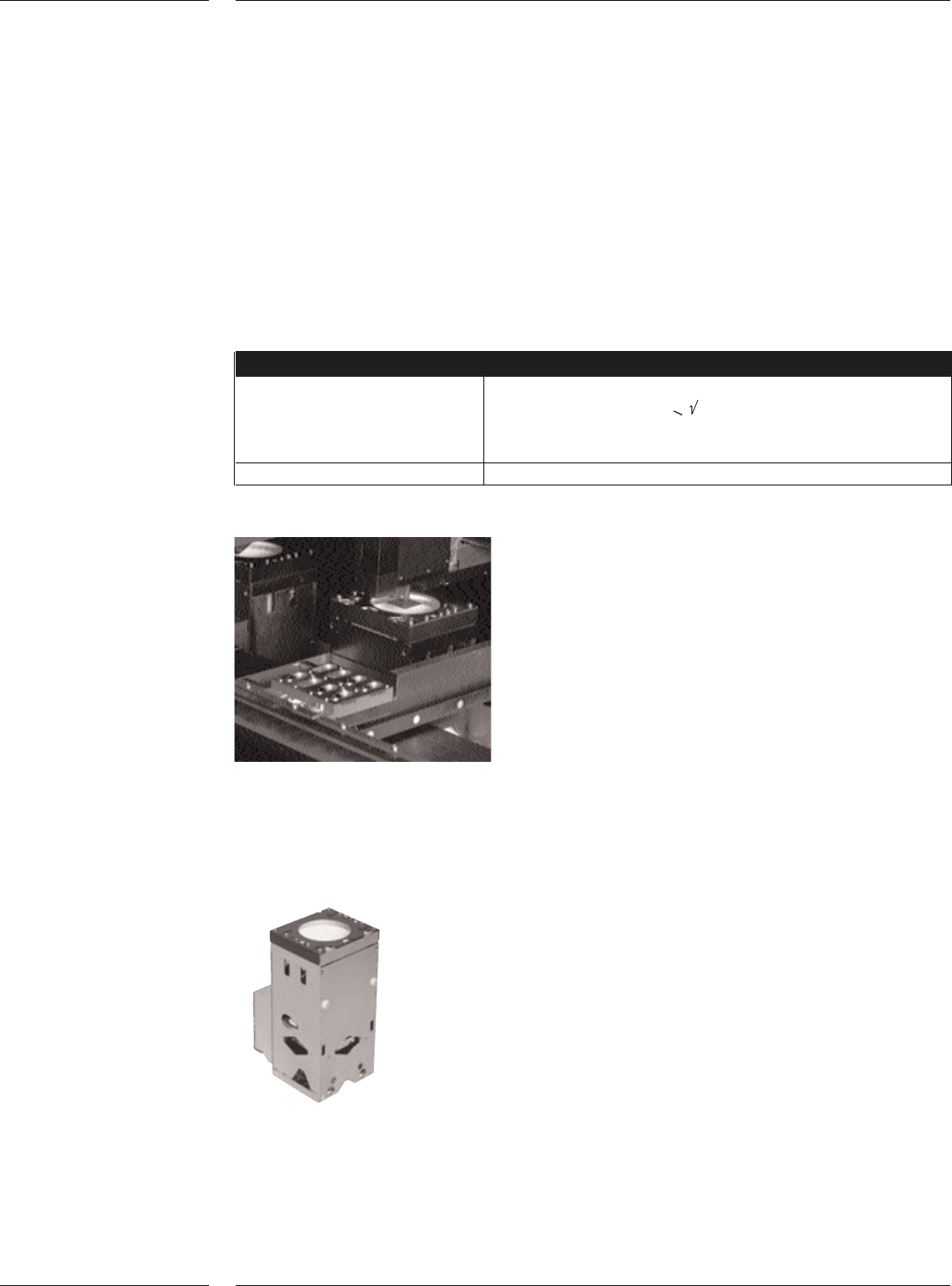
Vision alignment
Vision alignment is used for alignment of components on leads, edges or bumps.
Vision alignment is achieved by moving the component above the lens of an
upward-facing vision camera.
Alignment takes place at Z=0, which is the board level height.
Three light sources (dark field, midfield and bright field) ensure
sufficient contrast between the component (leads) and the
background. The illumination intensity is automatically chosen
based upon the reflectivity of the respective components. The
vision camera can determine the position of the component
with respect to a reference plate. The deviations, together with
the fiducial alignment values, will be used to determine the
correct placement position.
AX Component Vision camera
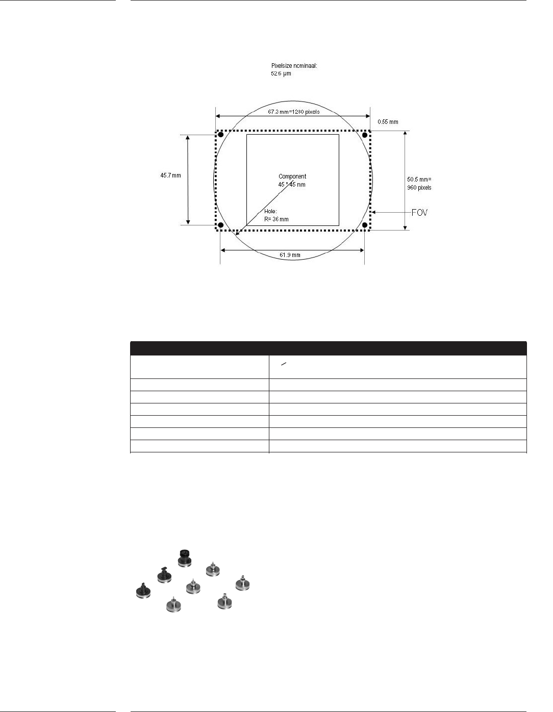
Camera field of view
Vision alignment
Component size > 2.0 x 1.25 mm
2
(0805 passives) to 45mm x 45mm
(1.77” x 1.77”)
Min. Lead width 0.200mm (0.005”)
Min. Lead pitch 0.400mm (0.012”)
Min. Bump size 0.300mm (0.012”) 0.150mm for size < 12x12mm
Min. Bump pitch 0.500mm (0.020”) 0.300mm for size < 12x12mm
Field of view (LxW) 67.8mm x 50.5mm
CCD Array resolution 1280 x 960 pixels
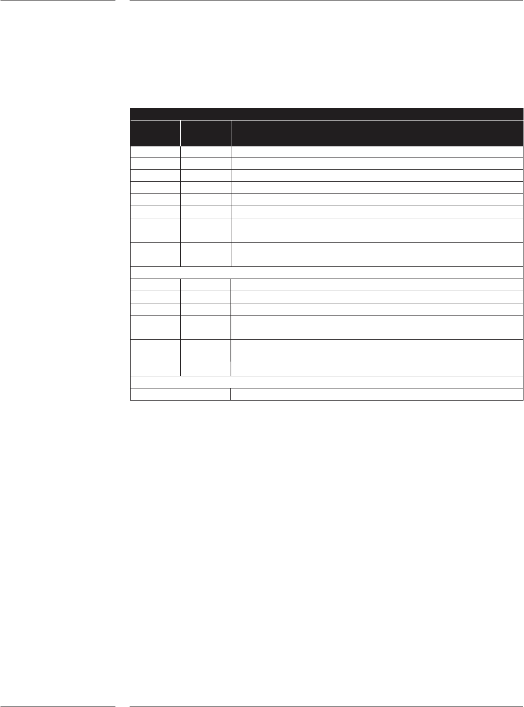
The AX System uses different nozzles to handle the component range from
0.4 x 0.2mm (01005) up to 45 x 45mm. The nozzles are designed to ensure
durability, minimal wear, whilst providing robust and delicate component handling.
The nozzles are connected to the placement head using a magnetic connection.
Various nozzle types of the AX
Figure 7
2.8 Toolbits
Figure 8
Features
12 of 34
The magnetic connection between nozzle and the placement head allows fast and
automatic exchange of the nozzle while ensuring a firm connection.
Standard nozzles
# nozzles Name Component range
per set
5 L1 01005-0201
5 L2 0201 - 0402
5 L3 0402 - 0603
5 L4 0603 - 0805 - 1206
5 L5 1206 - SO8 -SO16
5 L6 Melf; 1.00mm Ø 2.7mm
5 L7 CON10S1, All SO, SOJ, SSOP, TSSOP, VSO, QFP, TANT and
PLCC package types that comply with the nozzle dimensions.
5 L8 All SO, SOJ, SSOP, TSSOP, VSO, QFP, TANT and PLCC package
types that comply with the nozzle dimensions.
Set of Component Vision nozzles, consist of:
1 V3 Small non-ceramic components (BGA, Flip-chip etc.)
1 V4 Connectors
1 V5 Black, design L8 with extended length
1 V6 Black, design L8 with extra extended length for handling below
NCLA
1 V7 All BGA, SO, SOJ, SSOP, TSSOP, VSO, QFP, TANT and PLCC
package types that comply with nozzle-component size
relationship
Special nozzles
Nozzles made for other package types on request
Automatic nozzle detection and verification
At each program start-up and after each nozzle exchange, the component laser of
the placement head is used to measure and check the right type of nozzle. The
component laser also measures the exact nozzle orientation under the placement
head.
Contents
13 of 34