Spec of AX-3 AX-5 June 2005 LR.pdf - 第15页
The magnetic connection between nozzle and the placement head allows fast and automatic exchange of the nozzle while ensuring a firm connection. Standard nozzles # nozzles Name Component range per set 5 L1 01005-0201 5 L…
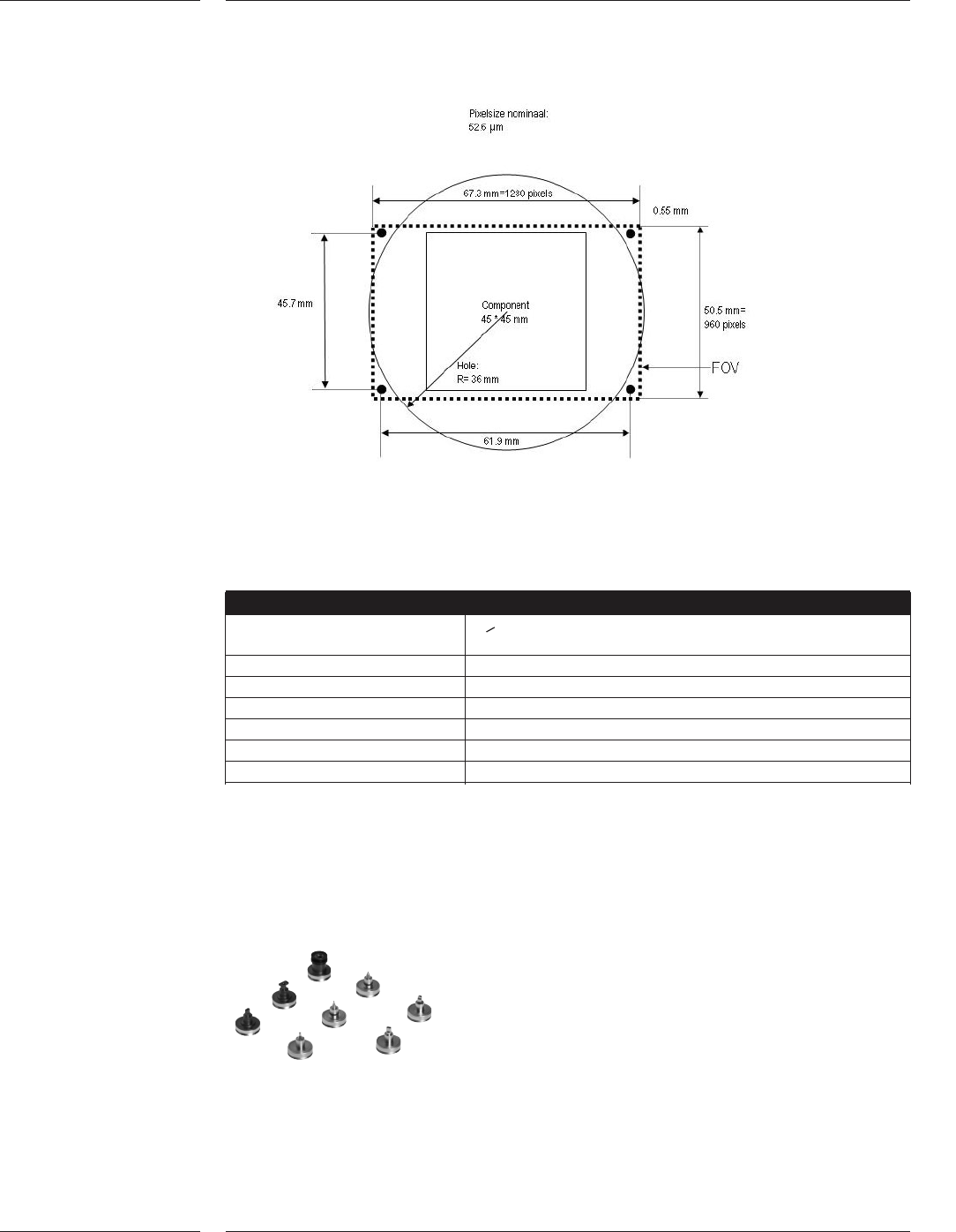
Camera field of view
Vision alignment
Component size > 2.0 x 1.25 mm
2
(0805 passives) to 45mm x 45mm
(1.77” x 1.77”)
Min. Lead width 0.200mm (0.005”)
Min. Lead pitch 0.400mm (0.012”)
Min. Bump size 0.300mm (0.012”) 0.150mm for size < 12x12mm
Min. Bump pitch 0.500mm (0.020”) 0.300mm for size < 12x12mm
Field of view (LxW) 67.8mm x 50.5mm
CCD Array resolution 1280 x 960 pixels
The AX System uses different nozzles to handle the component range from
0.4 x 0.2mm (01005) up to 45 x 45mm. The nozzles are designed to ensure
durability, minimal wear, whilst providing robust and delicate component handling.
The nozzles are connected to the placement head using a magnetic connection.
Various nozzle types of the AX
Figure 7
2.8 Toolbits
Figure 8
Features
12 of 34
The magnetic connection between nozzle and the placement head allows fast and
automatic exchange of the nozzle while ensuring a firm connection.
Standard nozzles
# nozzles Name Component range
per set
5 L1 01005-0201
5 L2 0201 - 0402
5 L3 0402 - 0603
5 L4 0603 - 0805 - 1206
5 L5 1206 - SO8 -SO16
5 L6 Melf; 1.00mm Ø 2.7mm
5 L7 CON10S1, All SO, SOJ, SSOP, TSSOP, VSO, QFP, TANT and
PLCC package types that comply with the nozzle dimensions.
5 L8 All SO, SOJ, SSOP, TSSOP, VSO, QFP, TANT and PLCC package
types that comply with the nozzle dimensions.
Set of Component Vision nozzles, consist of:
1 V3 Small non-ceramic components (BGA, Flip-chip etc.)
1 V4 Connectors
1 V5 Black, design L8 with extended length
1 V6 Black, design L8 with extra extended length for handling below
NCLA
1 V7 All BGA, SO, SOJ, SSOP, TSSOP, VSO, QFP, TANT and PLCC
package types that comply with nozzle-component size
relationship
Special nozzles
Nozzles made for other package types on request
Automatic nozzle detection and verification
At each program start-up and after each nozzle exchange, the component laser of
the placement head is used to measure and check the right type of nozzle. The
component laser also measures the exact nozzle orientation under the placement
head.
Contents
13 of 34
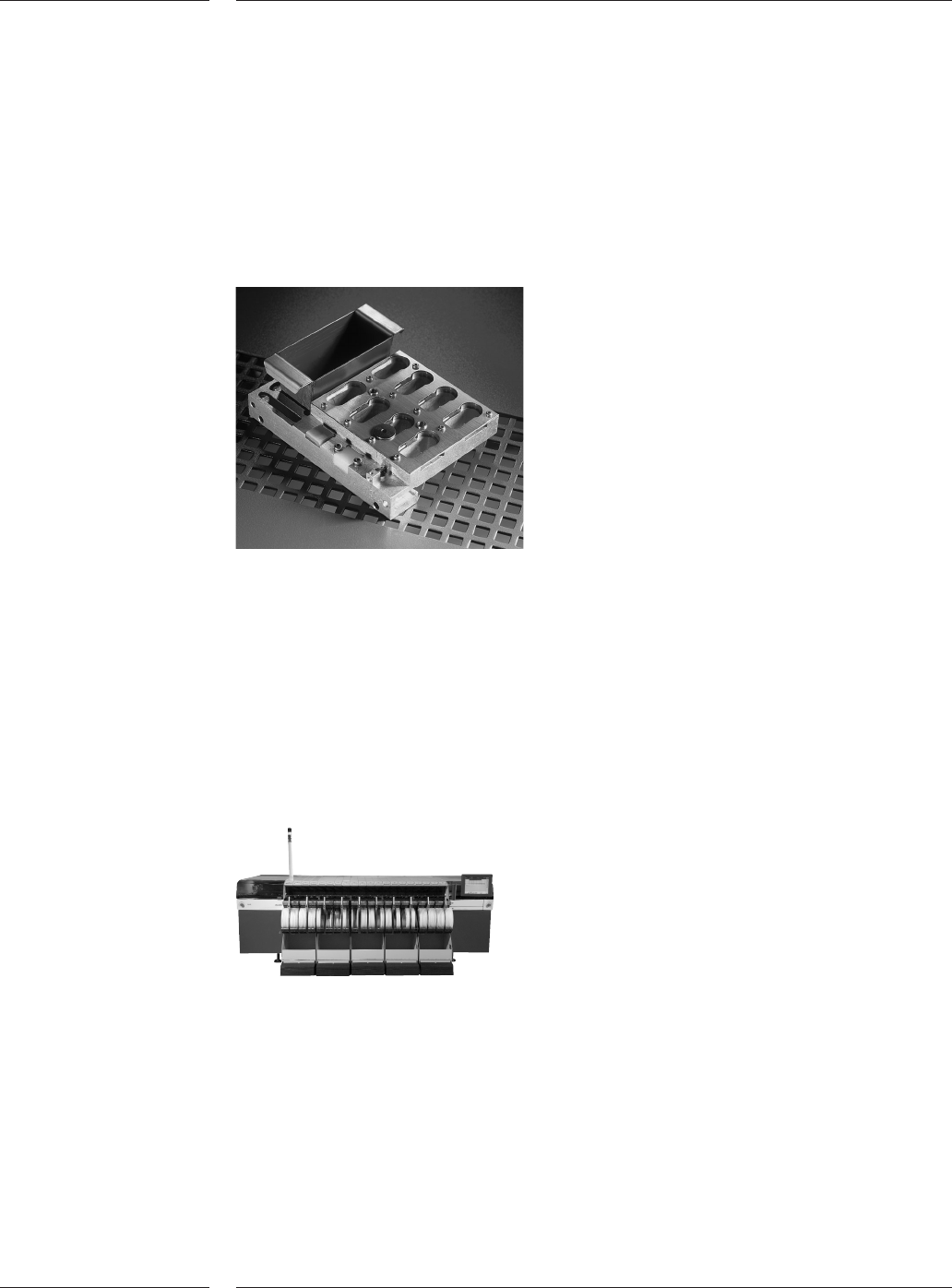
Each placement head has a toolbit exchange unit to exchange nozzles automa-
tically in about one second, while production continues. It also ensures maximum
flexibility for component range and family setup. Attached to the toolbit exchange
unit is a component dump bin, two toolbit vacuum check pads and a board
alignment camera calibration pad. The vacuum check pad is used for the
auto-matic calibration of the vacuum levels to assure reliable pick and placement
of components. Each toolbit exchange unit has eight different nozzle locations.
Toolbit exchange unit and dump bin
The AX System can be completely operated via a touch screen and a full Graphical
User Interface. The user interface complies to SEMI E95 to maximize ergonomics,
ease of usee amd minimize learning time.
Second user interface
Each AX System is supplied with one user interface at the front-right-hand side. On
the AX-5 a second user interface can be optionally mounted at the front-left-hand
side.
AX-5 machine
2.9 Toolbit
exchange unit
Figure 9
2.10 User interface
Figure 10
Features
14 of 34