00197551-01_MM_CPP-CP-Twin_Kunde_en.pdf - 第9页
Introduction 1.2.1 Calculation of Maintenance Intervals Maintenance Notes Maintenance Manual SIPLACE Placement Heads CPP, C &P20, Twin 9 1.2 1 . 2 M a in t e n a n c e N o t e s Maintenance Notes 1.2.1 1 . 2 . 1 C a …
Introduction
Safety Instructions 1.1.2 Safety Instructions for Maintenance Tasks
8 Maintenance Manual SIPLACE Placement Heads CPP, C&P20, Twin
1.1.2
1.1.2 Safety Instructions for Maintenance Tasks
Safety Instructions for Maintenance Tasks
Danger of burning
Ethanol
SIPLACE cleaning tissue
Consumables
Cleaning and lubri cation
1.1.3
1.1.3 Safety Instructions on Hazardous Materials
Safety Instructions on Hazardous Materials
WARNING
Danger of burning
► Never use inflammable fluids (e.g. alcohol) for cleaning purposes when working in the vi-
cinity of a naked flame or fire.
► Never spray lubricants or cleaning agents from aerosol cans in the vicinity of a naked flame
or fire.
CAUTION
Ethanol
► Always wear safety goggles and gloves when using concentrated ethanol to clean modules.
► If ethanol should accidentally get into your eyes, rinse your eyes immediately with water.
CAUTION!
SIPLACE cleaning tissue
Harmful: may cause lung damage if swallowed.
Do not inhale vapor / aerosol.
Avoid contact with the skin. If swallowed, do not induce
vomiting. See medical attention immediately and show
the packaging or label.
Wear latex gloves while using the cleaning tissue.
CAUTION
Consumables
Observe the safety data sheets for consumable materials!
CAUTION
Cleaning and lubrication
► Always use ethanol for cleaning – do not use solvents.
► Isopropanol – IPA can be used as an alternative.
► NEVER use compressed air to clean units inside the placement machine or modules.
CAUTION
Observe the safety data sheets
Observe the applicable safety data sheet, when handling hazardous materials (e. g. Loctite
241, ethanol).
Introduction
1.2.1 Calculation of Maintenance Intervals Maintenance Notes
Maintenance Manual SIPLACE Placement Heads CPP, C&P20, Twin 9
1.2
1.2 Maintenance Notes
Maintenance Notes
1.2.1
1.2.1 Calculation of Maintenance Intervals
Calculation of Maintenance Intervals
The SIPLACE maintenance intervals are time-based and set according to the following conditions:
▪ Shift model: eight hours per shift, three shifts per day, five days a week and 50 weeks a year.
▪ Real placement performance in accordance with machine specifications
▪ Environmental and production conditions: see document "Conditions at Installation Site"
1.2.1.1
1.2.1.1 Adjusting the Maintenance Intervals to Actual Production Conditions
Adjusting the Maintenance Intervals to Actual Production Conditions
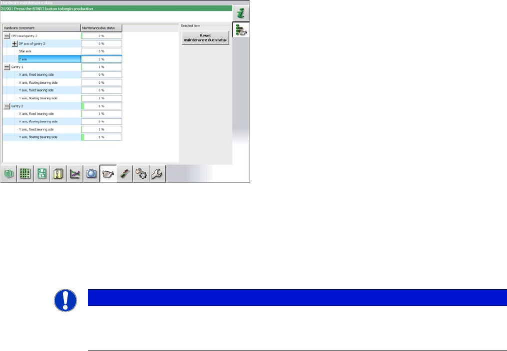
The maintenance status is calculated from the placement cycles, temperature and operating hours. The
status is shown as a progress bar (0 – 100 %).
Placement cycles for maintenance intervals:
▪ CPP: 40 mill. placed components
▪ C&P20: 30 mill. placed components
▪ C&P20A/M/P: 37.5 mill. placed components
Some customers want to adjust maintenance intervals to
their actual environment and production conditions. A
maintenance monitor can also be accessed in the station
software for some assemblies (from SW703.02).
The maintenance monitor is available for the following as-
semblies:
▪CPP
▪ C&P20/A/M/P
▪ X and Y axis (SX1/SX2/DX1/DX2 only)
NOTICE
Maintenance counter
► After maintenance has been completed, the maintenance counter needs to be reset for the
assembly concerned.
Introduction
Other Instructions 1.3.1 Environmentally-Friendly Disposal of Materials and Components
10 Maintenance Manual SIPLACE Placement Heads CPP, C&P20, Twin
1.3
1.3 Other Instructions
Other Instructions
1.3.1
1.3.1 Environmentally-Friendly Disposal of Materials and Components
Environmentally-Friendly Disposal of Materials and Components
SIPLACE products are manufactured using only materials and parts that can be easily separated and
disposed of in an environmentally-friendly way.
1.3.2
1.3.2 Use of Original SIPLACE Accessories and Spare Parts
Use of Original SIPLACE Accessories and Spare Parts
Only use original spare parts and authorized accessories. The use of other parts will affect safety and
will invalidate the liability for any consequential damage.
1.3.3
1.3.3 ESD Guidelines
ESD Guidelines
1.3.3.1
1.3.3.1 Definition of ESD
Definition of ESD
1.3.3.2
1.3.3.2 Important Measures to Protect Against Static Charging
Important Measures to Protect Against Static Charging
► Most plastics can easily become charged and must therefore be kept away from at-risk components.
► Always ensure that people, the workplace and packaging are safely earthed when handling electro-
static sensitive components.
1.3.3.3
1.3.3.3 Handling ESD Modules
Handling ESD Modules
Do not touch electronic modules unless it is absolutely essential to do so in order to carry out other work.
If it is necessary, make sure that you do not touch the pins or printed conductors when you pick up flat
modules.
Do not touch components unless
▪ You are constantly earthed by an ESD wrist strap or
▪ You are wearing ESD shoes or ESD shoe earthing strips on an ESD floor.
Always discharge yourself before you touch an electronic module. To do this, simply touch a conductive
and earthed object immediately before you touch the module (such as unpainted parts of a switch cab-
inet, a water pipe, etc.).
Do not allow modules with chargeable and highly insulating materials to touch one another, e.g. plastic
films, insulating table surfaces or items of clothing made from synthetic fibers.
NOTICE
Observe the applicable regulations
The company operating the system has sole responsibility for the proper, environmentally-
friendly disposal of machines, working materials, consumables and wear parts.
► Please observe your national statutory provisions for waste disposal and environmental
protection.
Almost all of the modules in use today are equipped with highly integrated MOS blocks and compo-
nents. The manufacturing techniques used mean that these electronic components are extremely sen-
sitive to overvoltage and thus to electrostatic discharge.
The abbreviation for such modules is 'ESD' (Electrostatic Sensitive Device). This is
used internationally, although the German abbreviation 'EGB' may also be seen. The
following symbol on cabinet rating plates, racks or packaging indicates that compo-
nents which are sensitive to electrostatic discharge have been used and thus that the
modules concerned are also touch-sensitive.
ESDs can be destroyed by voltages and power levels that are far below the level that can be perceived
by humans. Such voltages occur if a person touches a component or module without earthing them-
selves. Components that are exposed to such overvoltages do not generally appear to be defective im-
mediately - incorrect behavior starts after the component or module has been in operation for some
time.