5OM-1513-001_w.pdf - 第135页
4-22 5OM-1513 1 . PX-001 U50 (U52-CN1) Side ,PX-002 U50(U52-CN2) Side Ferrite Core Mounting Method U52-CN1 15 U52-CN1 U52-CN2 15 U52-CN2 2 . PX-001 U07 (X0701) Side PX-005 U09(X0901) Side Ferrite Core Mounting Method X07…
4-21
5OM-1513
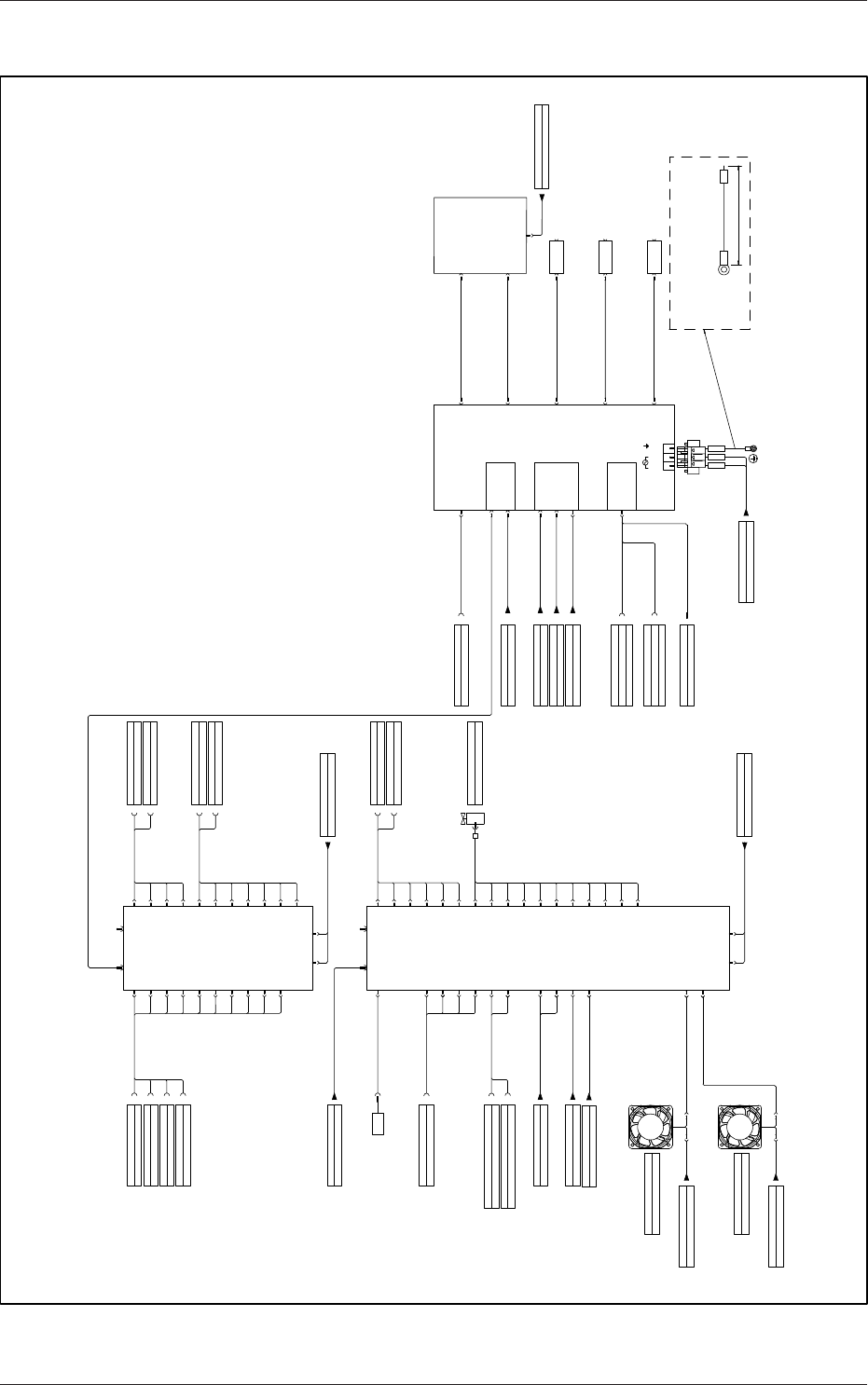
机械周围导线连接图 1
0908-001-(2090001012-1)
X0703
PX-170
U07
CN11
X0711
CN10
X0710
CN12
X0712
Harness PX-052:Connect to X1060
PX-163
PX-188
CN15
X0715
CN16
X0716
CN17
X0717
CN42
X0742
Harness PX-189:Connect to X1065
CN3
X0704
CN4
X0701
CN1B
X0702
CN2B
(UB32)
PX-001
CN13
X0713
CN14
X0714
CN30
X0730
CN31
X0731
CN32
X0732
CN33
X0733
CN25
X0725
X1060
X1064
Harness PX-052:Connect to X1064
X106F
Harness PX-122:Connect to X106F
X1070
Harness PX-052:Connect to X1070
X1065
X107C
Harness PX-189:Connect to X107C
CN18
X0718
PX-166
CN19
X0719
CN20
X0720
Harness PX-167:Connect to X1068
X1068
X1078
Harness PX-167:Connect to X1078
CN38
X0738
CN39
X0739
CN40
X0740
CN41
X0741
HarnessPX-170
X0903
PX-086
U09
CN11
X0911
CN10
X0910
CN12
X0912
PX-087
PX-191
CN19
X0919
CN20
X0920
CN40
X0940
CN41
X0941
Harness PX-192:Connect to X1089
CN3
X0904
CN4
X0901
CN1B
X0902
CN2B
(UB32)
PX-005
CN13
X0913
X0914
X1089
X109A
Harness PX-192:Connect to X109A
CN43
X0943
CN25
X0925
CN30
X0930
CN31
X0931
CN32
X0932
CN33
X0933
Harness PX-086
Harness PX-005
Solvent Shortage Alarm
B80
PX-088
CN14
B80
CN15
X0915
PX-090
CN16
X0916
Harness PX-089:Connect to X1081
X1081
Shutter Change-Over Cleaning Suction Side Connect to B85
B85
B86
Shutter Change-Over Chuck Suction Side Connect to B86
CN44
X0944
PX-179
CN45
X0945
Harness PX-179
CN42
X0942
CN34
X0934
CN35
X0935
CN36
X0936
CN37
X0937
CN38
X0938
CN39
X0939
Y90
Electroneumatic Regulator Connect to Y90
CN21
X0921
PX-027
CN22
Harness PX-027
X0922
CN23
X0923
PX-028
Harness PX-028
M06
M06
(CNDC24Z7Q)
PX-048
Harness PX-048
X06
PX-030
M07
M07
(CNDC24Z7Q)
PX-049
Harness PX-049
X07
CN24
X0924
PX-031
U50
(APL3000-BA-CM18-4P-5M)
L N FG
L104
L204
PX-175
Harness PX-175
Attached connector
Note 5
Note 6
COM1
U50-COM1
PX-016
Harness PX-019:Connect to X2530
X2530
CN1
U52-CN1
PX-001
CN2
Harness PX-002
PX-002
U52-CN2
U52
CN1
U53-CN1
PX-006
CN2
Harness PX-013
PX-013
U53-CN2
U53
Harness PX-006
CN3
Harness PX-162
PX-162
U53-CN3
DVI-I
U50-DVI
H00
(R10UH)
DVI-D
H00-DVI
USB1 USB
H00-USB
USB2
N80-USB1
PX-159
H00-PW
POWER
1090008007-02 Item No.057
Harness PX-159
U50-USB1
U50-USB2
N80
LAN1
N81-LAN1U50-LAN1
N81
LAN2
N82-LAN2U50-LAN2
N82
XU01
U51
X1B04
X3B03
Camera Cable1GG4W20049090
Connect to X3B03
Camera Cable1GG4W20047040
Connect to X1B04
X1G03
HarnessPX-176:Connect to X1G03
Note 6
Note 1
Note 2
Note 3
Note 4
Note 7
Cooling Fun M06
Cooling Fun M07
150
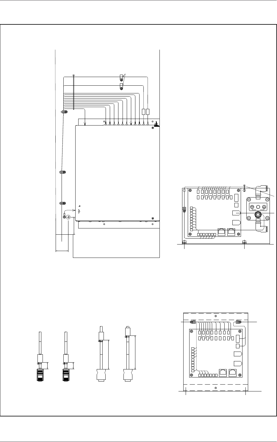
4-22
5OM-1513
1.PX-001 U50 (U52-CN1) Side ,PX-002 U50(U52-CN2) Side Ferrite Core Mounting Method
U52-CN1
15
U52-CN1
U52-CN2
15
U52-CN2
2.PX-001 U07 (X0701) Side PX-005 U09(X0901) Side Ferrite Core Mounting Method
X0701
X0701
X0901
80
X0901
60
U50
U52-CN1
U52-CN2
U53-CN1
U53-CN2
U53-CN3
XU01
U52-DVI
Control Board Upper Surface
U50-USB1
U50-USB2
U50-LAN1
U50-LAN2
U50-COM1
L N FG
Ferrite Core
Specification (Management Point)
Note
Ferrite Core
4.U07 Mounting Diagram
U07
4 4
5.U09 Mounting Diagram
U09
Y90
Attached Connector
38
50
机械周围导线连接图 2
0908-001-(2090001012-2)
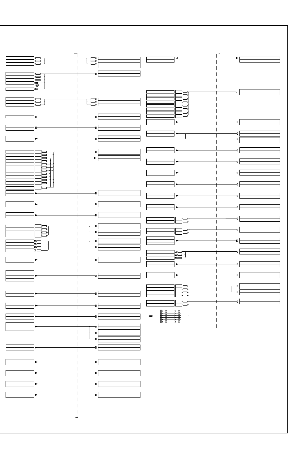
4-23
5OM-1513
控制盘外导线连接图 1
0908-001-(1090008007-2)
Harness PX-058:Connect to X3011
L=2700(1510)
Switch Box Section Right Rear Side Safety Door Unlock Switch :Connect to X1011
X1011
X3011
PX-075
L=2700(1790)
X0516
B46
Main Body Section PEC Recognition Y-Axis Interlock Sensor:Connect to B46
I/O PCB U05:Connect to CN16
144
145
187
197
198
199
200
10B
Terminal Block
PX-033
L=2800(1700)
Safety Door Switch Right Rear Side:Connect to S14
S14
144
145
187
197
198
199
200
10B
Terminal Block:TB3 Insert it to 144
Terminal Block:TB3 Insert it to 145
Terminal Block:TB3 Insert it to 187
Terminal Block:TB3 Insert it to 197
Terminal Block:TB3 Insert it to 198
Terminal Block:TB3 Insert it to 199
Terminal Block:TB3 Insert it to 200
Terminal Block:TB3 Insert it to 10B
PX-134
L=3200(2280)
A33-CN3
B331
Driver A33:Connect to CN3
Main Body Section PEC Recognition Y-Axis Origin Sensor:Connect to B331
B334
L=2400(1510)
Main Body Section PEC Recognition Y-Axis Rotational Origin Sensor:Connect to B334
Inside the Control Panel Main Body Side
Left Side Opening
Section
PX-100
L=1600(990)
M19
Driver A19:Connect to CN1
Main Body Section Table X-Axis Motor M19:Connect to M19
A19-CN1
PX-101
L=1200(600)
A19-CN3
X195
Driver A19:Connect to CN3
Main Body Section Table X-Axis Motor M19:Connect to X195
PX-043
Air Pressure Detection Sensor Front Side:Connect to S15
191
24A1
Relay K315:Connect to Terminal NO.1
Relay K315:Connect to Terminal NO.8
10A
Relay K320:Connect to Terminal NO.A2
S15
L=2900(1800)
PX-078
L=2900(1730)
X0520
B4A
Front Side Cover Vacuum Switch:Connect to B4A
I/O PCB U05:Connect to CN20
X0534
PX-082
L=3000(1800)
Y54
I/O PCB U05:Connect to CN34,CN35
Front Side Cover PCB Width Clamping Solenoid Valve:Connect to Y54
PX-159
L=3800(2780)
H00-PW
Touch Panel H00:Connect to Power Connector
24A3
Terminal Block
10A
24A3
10A
Terminal Block:TB3 Insert it to 24A3
Terminal Block:TB3 Insert it to 10A
PX-048
L=4000(3280)
M06
Main Body Section Cooling Fan M06:Connect to M06
193
Terminal Block
10B
193
10B
Terminal Block:TB3 Insert it to 10B
Terminal Block:TB3 Insert it to 193
PX-049
L=2800(1640)
M07
Main Body Section Cooling Fan M07:Connect to M07
193
Terminal Block
10B
193
10B
Terminal Block:TB3 Insert it to 10B
Terminal Block:TB3 Insert it to 193
X0236,X0237
I/O
PCB
U02
PX-060
Main Body Section Light Tower:
Connect to
H24
H24
L=4700(3250)
PX-098
L=850(290)
A19-CN4
X191
Driver A19:Connect to CN4
Main Body Section HarnessPX-099:Connect to X191
A29-CN4
L=2200(1630)
X291
PX-127
L=2950(2260)
M29
PX-129
Driver A29:Connect to CN4
Main Body Section Harness PX-128:Connect to X291
A29-CN1
Driver A29:Connect to CN1
Main Body Section Stencil Y-Axis Motor M29:Connect to M29
PX-135
L=3500(2650)
A33-CN6
M33
Driver A33:Connect to CN6
Main Body Section PEC Recognition Y Motor M33:Connect to M33
PX-023
L=2500(2000)
Main Power Section HarnessPX-022:Connect to M01
M01
PX-174
L=2000(1900)
Main Power Section Noise Filter Z02 Connect to Terminal NO.1
Breaker Q202:Connect to Terminal NO.2
Contactor K204:Connect to Terminal NO.2
L=3200(2650)
X11
Main Power Section Safety Door Unlock Switch S05,H05:Connect to X11
X0225
PX-059
L=3000(2300)
F101
Green/Yellow
L102
L202
L302
Breaker Q202:Connect to Terminal NO.4
Breaker Q202:Connect to Terminal NO.6
L102
L202
L302
Main Power Section Noise Filter Z02 Connect to Terminal NO.2
Main Power Section Noise Filter Z02 Connect to Terminal NO.3
L111
L211
L311
Contactor K204:Connect to Terminal NO.4
Contactor K204:Connect to Terminal NO.6
K204Fix it with a screw onto the lower tap (For grounding)
K204 Fix it with a screw onto the lower tap (For shielding)
Blue
Main Power Section Lightning Surge Protective Fuse F101~301:Connect to F101
I/O PCB U02:Connect to CN25
140
141
142
143
186
195
196
197
200
201
202
10B
Terminal Block
PX-029
L=4600(3520)
Terminal Block:TB3 Insert it to 140
Left Front Shutter Open Check Switch:Connect to S13
140
141
142
143
186
195
196
197
200
201
202
S13
Terminal Block:TB3 Insert it to 141
Terminal Block:TB3 Insert it to 142
Terminal Block:TB3 Insert it to 143
Terminal Block:TB3 Insert it to 186
Terminal Block:TB3 Insert it to 195
Terminal Block:TB3 Insert it to 196
Terminal Block:TB3 Insert it to 197
Terminal Block:TB3 Insert it to 200
Terminal Block:TB3 Insert it to 201
Terminal Block:TB3 Insert it to 202
Terminal Block:DC2 Insert it to 10B
10B
PX-024
L=5000(3950)
S12
Left Front Safety Door Switch:
Connect to
S12
X03
PX-027
L=2400(680)
X0921
X0922
Left Side Cooling Fan M03:Connect to X03
I/O PCB U09:Connect to CN21
I/O PCB U09:Connect to CN22
X04
Right Side Cooling Fan M04:Connect to X04
PX-028
L=1300(680)
X0903
PX-179
L=2000(1050)
X0904
I/O PCB U09:Connect to CN3
I/O PCB U09:Connect to CN4
24B1
Terminal Block
10B
24B1
10B
Terminal Block:TB3 Insert it to 24B1
Terminal Block:TB3 Insert it to 10B
24B1
24B1
10B
10B
L=1100(580)
X0901
PX-005
X0202
I/O PCB U02:Connect to CN2B
I/O PCB U09:Connect to CN1B
L=1500(530)
PX-086
X0944
X0945
I/O PCB U09:Connect to CN44
I/O PCB U09:Connect to CN45
944
Relay K9E:Connect to Terminal NO.1
24B1
945
Relay K9E:Connect to Terminal NO.1
24B1
Relay K9E:Connect to Terminal NO.8
Relay K9E:Connect to Terminal NO.8
L=750(285)
PX-079
Table Section HarnessPX-093:Connect to X104C
X104C
X0522,X0523
I/O PCB U05:Connect to CN22,CN23
Controller U17:Connect to CN1
PX-091
L=750(215)
X171
Table Section HarnessPX-093:Connect to X171
A37-CN2
L=2800(1470)
X371
PX-141
L=2800(1430)
M37
PX-145
Driver A37:Connect to CN2
A37-CN7
Driver A37:Connect to CN7
L Conveyor HarnessPX-142:Connect to X371
L Conveyor Width Axis Motor M37:Connect to M37
L=2900(1470)
M41
PX-151
A45-CN7
Driver A45:Connect to CN7
L Conveyor PCB Transfer 1 Motor M41:Connect to M41
L=2900(1440)
X430
PX-152
A45-CN8
Driver A45:Connect to CN8
L Conveyor HarnessPX-153:Connect to X430
PX-073
L=1300(835)
B40
L Conveyor PCB Transfer Check Sensor:Connect to B40
B41
L Conveyor PCB Check Sensor:Connect to B41
B42
L Conveyor PCB Stopper Upper Limit:Connect to B42
L=1300(785)
PX-080
L Conveyor PCB Stopper Y50:Connect to Y50
Y50
X0530,X0531
I/O PCB U05:CN30,CN31
A19-CN5
PX-104
L=1550(800)
X210
Table Section HarnessPX-105:Connect to X210
A19-CN7
L=1550(810)
PX-106
Driver A19:Connect to CN5
Driver A19:Connect to CN7
X1215
Table Section HarnessPX-107:Connect to X1215
L=1750(930)
X211
PX-102
A19-CN8
Driver A19:Connect to CN8
Table Section HarnessPX-103:Connect to X211
A17-CN1
PX-021
L=850(300)
Control Board Upper Side DCPowerG05 Connect to Terminal NO.L1
Breaker Q202:Connect to Terminal NO.1
L105
L205
L305
Breaker Q202:Connect to Terminal NO.3
Breaker Q202:Connect to Terminal NO.5
L105
L205
L305
Control Board Upper Side DCPowerG05 Connect to Terminal NO.L2
Control Board Upper Side DCPowerG05 Connect to Terminal NO.L3
PX-056
G05-CN02
X0216
PX-061
L=1100(340)
Control Board Upper Side DCPowerG05 Connect to CN02
I/O PCB U02:Connect to CN16
PX-057
Harness PX-058:Connect to X2011
X2011
X0512
X0510,X0511
I/O PCB U05
Connect to CN10,CN11,CN30
Inside the Control Panel Main Body Side
X0234,X0235
Connect to CN34,CN35,CN36,CN37
Terminal Block:TB3 Insert it to 24B1
Terminal Block:TB3 Insert it to 10B
AC Servo amplifier A23:Connect to CN1
Relay
Connect to
K310,K3170,K3171
U17-CN1
Right Side Opening
Section
PX-170
L=3050(2000)
X0703
X0704
I/O PCB U07:Connect to CN3
I/O PCB U07:Connect to CN4
24A3
10A
24A3
10A
Terminal Block:TB3 Insert it to 10A
24A5
24A5
Terminal Block:TB3 Insert it to 24A5
10A
10A
Terminal Block:DC2 Insert it to 10A
Terminal Block:TB3 Insert it to 24A3
Terminal Block
24A3
TB3
Red
24A3
24A1
24A1
10B
10B
10B