5OM-1513-001_w.pdf - 第87页
综合模块图 0908-001-(M900W A---2001) DVI-I LAN2 LAN1 USB2 USB1 Operation Panel Section LCD Control Box Section 3 ~ M Blower Motor CN1 CN2 M R Conveyor L Conveyor PCB Chuck & T able Section 3 ~ M M M PG 1 ~ M PEC Recogniti…
3-7
5OM-1513
0908-001
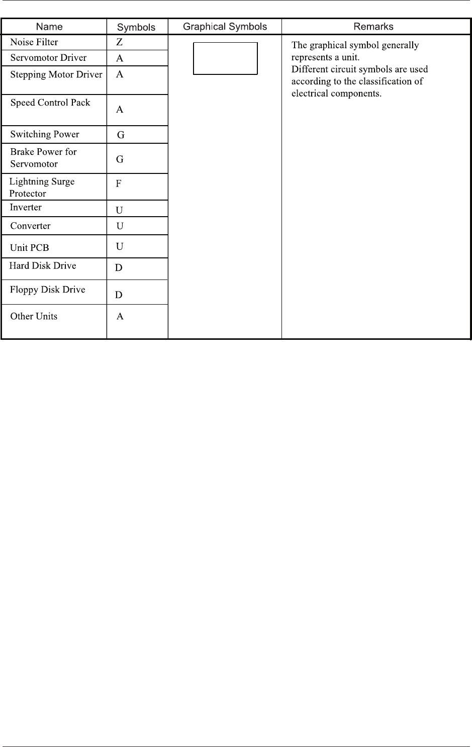
电路图符号
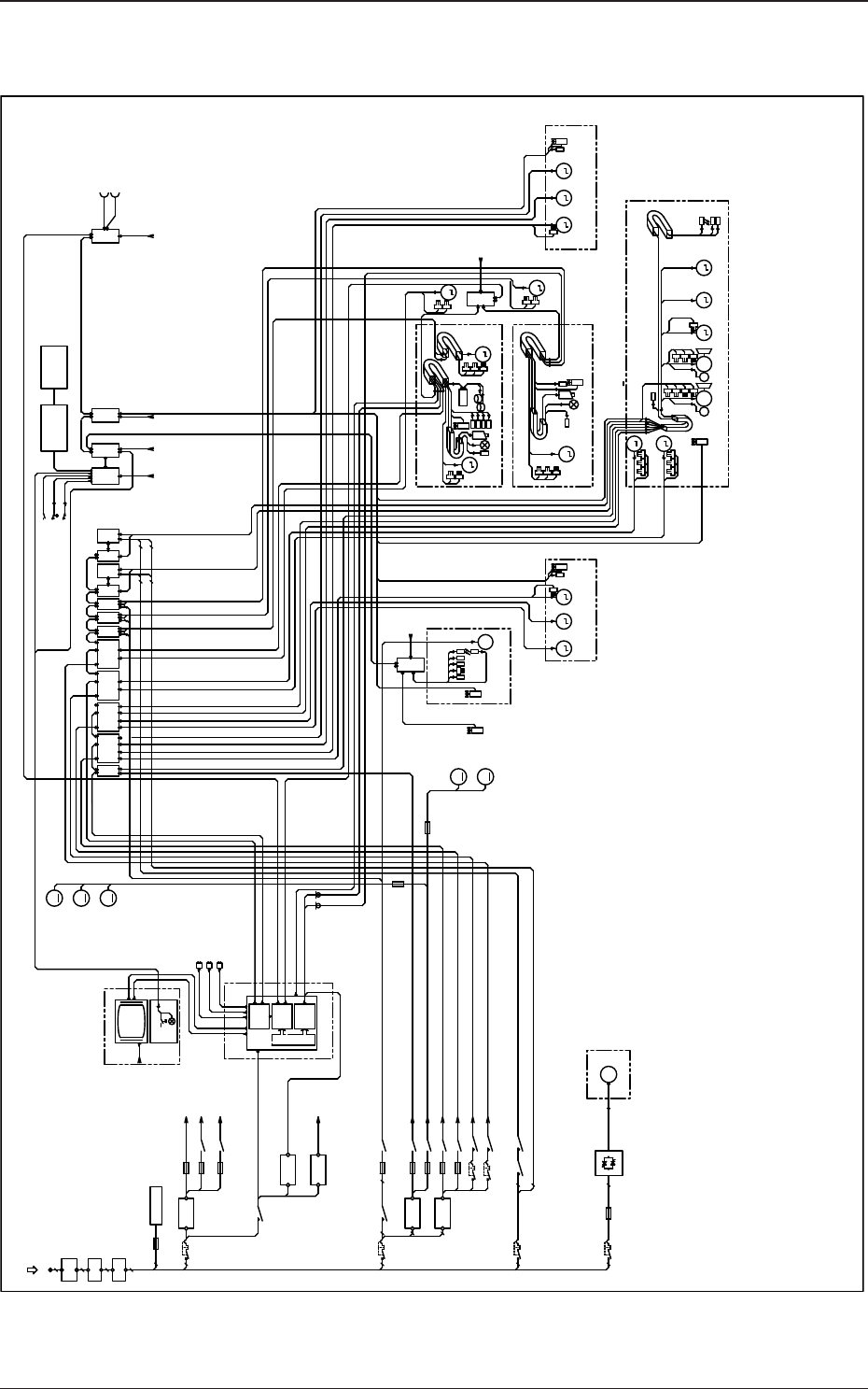
综合模块图
0908-001-(M900WA---2001)
DVI-I
LAN2
LAN1
USB2
USB1
Operation Panel Section
LCD
Control Box Section
3~
M
Blower Motor
CN1
CN2
M
R Conveyor
L Conveyor
PCB Chuck & Table Section
3~
M
M
M
PG
1~
M
PEC Recognition Section
M
Squeegee Head
Section
M
M31
B03
Load Cell
Amplifier
M27
M
Stencil Y Axis
M29
Squeegee Driving Axis
M
M
N80
N81
N82
LAN2
LAN1
USB
Signal from
Input Machine
Signal from
Output Machine
CN2
Y90
Stencil Recognition Camera
(Option)
CN1
COM1
M M
M
3~
M
PG
M M
M M
M
24B1
24B1
24B3
48F1
48F3
48F5
48F7
24A1
24A3
24A5
24A3
12C
24A3,A5
24A3,A5
24A1
24A3,A5,A7
24E
24A3,24E
3
3
3
3
3
2
3
3 3
2
3 3
2
3
3
2 2 2
3
2
2
3
2
3F AC200V
Z02
NOISE
FILTER
FILTER
NOISE
Z01
Q200
F101-301
V01
Q201
+24V(A)
G01
F01
F02
K06
F03
K08
K201
H00
U50
U52
U53
U51
+12V(C)
G03
+24V(E)
G04 24E
Q202
K202
+24V(B)
G02
F04
K06
+48V(F)
G05
F06
F07
K09
K09
Q205
K18
Q206
K19
Q203
K203A K203B
Q204
F110,F210,F310
K204
F10
F200
K2E
Box Computer
DC Load
Pulse Motor Driver
M
M06
M01
M
M07
M
M03
M
M04
M
M05
F11
F05
K08
Lightening Surge Protector
RS485
PCI Bus
HLSC
Recog-
nition
Touch Panel
Main Power Supply
Control Power Supply
A45
A37
Driver
A25
A19
A29
Driver
A33
A35
Driver
Driver
Driver
Driver
A27
Driver
Driver
Controller
U23
A23
Servo
amplifir
U17
A17
M41M37
Conveyor
Width
PCB
Transfer 1
M43 M37
Conveyor
Width
PCB
Transfer 2
Table Q-Axis
PCB Backup
U/D Axis
Table Z-Axis Rail Width
Axis
Table X-Axis
M21
M23M17 M25
M19
M02
PEC Recognition X Axis PEC Recognition Camera
PEC Recognition
Y Axis
M35
M33
Cleaning Section
M43
PCB
Transfer 2
M41
PCB
Transfer 1
Chute PCB
Transfer 1
M49 M51
Chute PCB
Transfer 2
Electroneumatic
Regulator
Relay Board
U54
Emergency Stop Front Rear
Safety Cover Front Rear Cleaning Section
B04
Load Power
Contactor Relay
Q201 to Q206 CB Contact Monitor
Servo-Motor
Main Power
Circuit
Contactor
Operation
Swich
U05
16in16out
U03
Front and Rear
I/F Sections
U09
16in16out
U07
16in16out
U02
16in16out
Controller
Servo
amplifir
Stencil
Recognition
X Axis
(Option)
3-8
5OM-1513
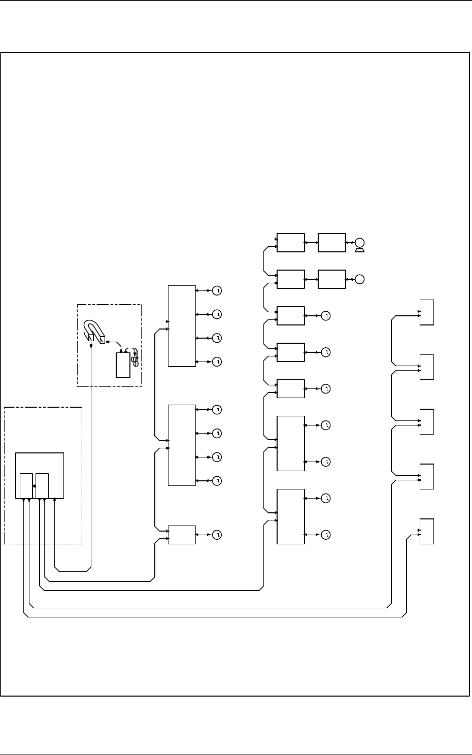
省配线系统图
0908-001-(M900WA---2002)
Address Setting
0
Address Setting
1
Address Setting
2
Address Setting
3
Address Setting
4
Address Setting
5
Address Setting
6
Address Setting
7
Address Setting
8
Address Setting
9
Address Setting
12~15
Address Setting
16~19
Address Setting
7
Address Setting
3
Address Setting
5
Squeegee Head Section
M
M27
M M
M
M41
M
M43
M
M49
M
L
Convey
or
R
Convey
or
M M M
M37 M37 M41 M43
R Conveyor
PCB
Transfer 1
M
M51
M
Chute Width
Changeover
M25
Table
Z-Axis
M17
3~
M
M33 M35
M
Table X-Axis
M19
M
M21
M
M29
M
M31
PCB
Up/Down
Axis
M23
3~
M
COM1
Control Box
A27
Driver
Driver
Driver
U05
16in16out
A53
(Option)
PCB Transfer
Section io
PCB Chuck Section io
U03
8in8out
Front and Rear
I/Fs Section io
U02
16in16out
X0201 X0202X0305 X0901
U53-CN1
Load Cell Amplifer
U52
N1 N2 N1 N2
A45
Driver
N1 N2
N1 N2
A37
Driver
N1 N2
HLSC
U52-CN1
40
U53
RS485
U53-CN2
CN7 CN8 CN9
CN10
A25
Driver
N1 N2
CN7 CN8 CN9
CN10
CN4
U17
Pulse
Controller
N1 N2
U23
Pulse
Controller
N1 N2
A17
Driver
X0501 X0502
16in16out
X0701
U07
Squeegee Head
Section io
PEC Recognition Section io
16in16out
Box Computer
U50
A33
A35
A19
Driver
N1 N2
A29
Driver
N1 N2
U09
X0304
A23
Driver
U52-CN2
R Conveyor
PCB
Transfer 2
L Conveyor
PCB
Transfer 1
L Conveyor
PCB
Transfer 2
Chute
PCB
Transfer 1
Chute
PCB
Transfer 2
Table Q-Axis
Stencil
Recognition
Y-Axis
Stencil
Recognition
X-Axis
Squeegee
Driving Shaft
PEC
Recognition
Y-Axis
PEC
Recognition
X-Axis
Address Setting
2
Operation Panel
Section io
Relay Circuit Section io
Address Setting
9
Printing Pressure
Control Section io
Cleaning Section io
3-9
5OM-1513