5OM-1513-001_w.pdf - 第78页
5OM-1513 0908-001 3-A 第三章 电路图 本章节就各电路图进行说明。 因含有一定的难度,参考时请充分注意。
0908-001
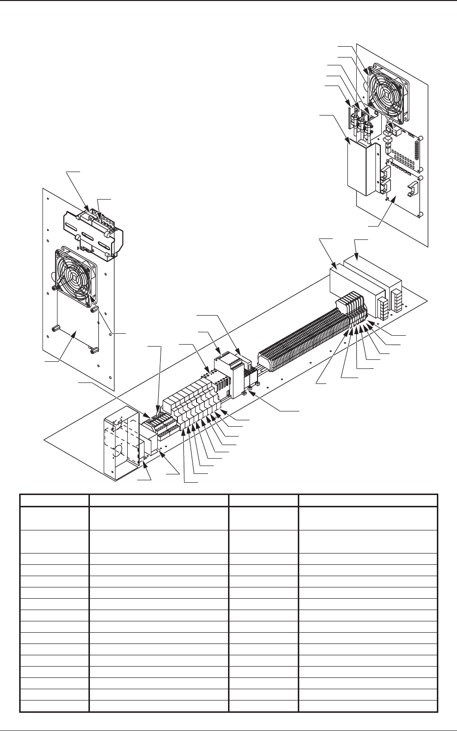
控制盘 ( 左侧面、右侧面、底面 )
Symbols Name Symbols Name
M03 Fan on the Control Panel
Lef Sidet
U02
I/O PCB
M04
Fan on the Control Panel
Right Side
U03 Front and Rear I/Fs
G01 DC24V Power Supply (A) U54 Relay Board
G02 DC24V Power Supply (B)
G03 DC24V Power Supply (C)
G04 DC24V Power Supply (D)
Left Side
Right Side
Bottom Side
M03
U03
M04
K300
K301
K23B
K3231
U02
U54
F110
F210
F310
R17B
G02
G01
K310
K320
K08
K07
K315
K3121
K3133
K3132
K3131
K3123
K3122
K3171
K17B
F10
F11
F04
F02
F05
F03
G03
G04
F01
K3230
K117
K10
K06
K3170
K23
K9E
K9F
2-20
5OM-1513

5OM-1513
0908-001 3-A
第三章
电路图
本章节就各电路图进行说明。
因含有一定的难度,参考时请充分注意。

5OM-1513
0908-001 3-B