00191471-01.pdf - 第23页
Servicing Instructions HS-50 Replacing the Y-Ax is Sca le 01/99 Issue 23 à Pu sh the two gant ries to the right so tha t you can detach the re st of th e scale . CAUTION 3 When wo rking ne ar the slee ve (item 3 in F ig.…
Replacing the Y-Axis Scale Servicing Instructions HS-50
01/99 Issue
22
à Put on a pair of protective gloves.
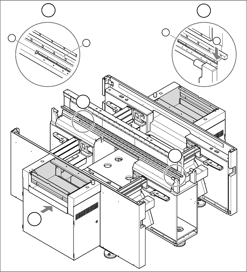
à Starting from the right-hand side of the placement system, use the firmer chisel (item 2 in Fig.
3 - 2) to detach the y axis scale (item 1 in Fig. 3 - 2) from the contact surface. Work along the
scale until you reach the two main gantries on the left-hand side.
3
Fig. 3 - 2 Removing the y axis scale
(1) Scale for the y axis (2) Starting point for firmer chisel
(3) Sleeve (4) Guide rail of y axis recirculating ball screw unit
T PCB transport direction 33
T
B
A
B
3
4
A
1
2

Servicing Instructions HS-50 Replacing theY-Axis Scale
01/99 Issue
23
à Push the two gantries to the right so that you can detach the rest of the scale.
CAUTION 3
When working near the sleeve (item 3 in Fig. 3 - 2), use the firmer chisel carefully so as not
to damage the sleeve. 3
à Remove the scale.
CAUTION 3
Be careful not to catch or twist the scale when you remove it. 3
à Use the firmer chisel to remove glue residues from the contact surface.
à Remove any remaining glue residues with the multiflex pad.
à Clean the contact surface using a lint-free cloth impregnated with ethyl alcohol.
ATTENTION 3
The contact surface has to be totally free of glue residues. 3
3
3

Replacing the Y-Axis Scale Servicing Instructions HS-50
01/99 Issue
24
3.4 Fitting the y axis scale
à Movethetwogantriestotheright.
à Leave the scale in its transparent packaging film and insert so that the hole in the scale is on
the left.
à Pull the transparent packaging film back slightly.
à Pull away approximately 5 cm of the film covering the adhesive strip on the back of the scale.
à Attach the scale so that the sleeve (item 3 in Fig. 3 - 2) slides into the hole in the scale.
à Place one of the two guides immediately to the right of the sleeve onthe guide rail of the y axis
recirculating ball screw unit (item 4 in Fig. 3 - 2) and fix in place with the screw.
à Move the two main gantries approximately 10 - 20 cm to the left.
à Pull away all the transparent film.
à Attach the second guide on the right-hand side of the guide rail of the y axis recirculating ball
screw unit and then fix the scale in the correct position.
CAUTION 3
Make sure that the scale is not twisted. 3
à Push the two main gantries as far as possible to the right.
à Remove the long pin from the pasting device.
à Insert the pasting device into the guide rail of the y axis recirculating ball screw unit (item 4 in
Fig. 3 - 2) on the left-hand side.
à Insert the long pin into the pasting device so that the scale runs between the two guide pins of
the pasting device and the long pin.
à Place the protective film of the adhesive tape of the tape measure around the long pin, pull to
the right and tighten with your right hand.
à With your left hand, press against the roller of the pasting device.
à Hold the protective film with your right hand and pull to the right in order to move the pasting
device to the right.
à Remove the long pin from the pasting device.
à Lift the pasting device from the guide rail of the y axis recirculating ball screw unit.
à Move the two main gantries all the way to the left.
à Return the pasting device to the position from which you removed it.
à Insert the long pin into the pasting device so that the scale runs between the two guide pins of
the pasting device and the long pin.