00194474-0702_AI_HeadReconfig_X_605_DE+EN.pdf - 第164页
2 Assembly Instructions - SIPLACE X-Series Head Reconfiguration Kits Head Reconfiguration Kits 07/2010 Edition 164 : Remove the large reject bin for the T winHead. 2 On the subject of the reject bin sensor , also read th…
Head Reconfiguration Kits 2 Assembly Instructions - SIPLACE X-Series Head Reconfiguration Kits
07/2010 Edition
163
2
Wear an ESD armband for the whole time you are working on the placement head and servos.
2
2
2
Remove the axis cards and servo cards.
Please note the overviews in the appendix Chapter 2.14.1 or Chapter 2.14.2. 2
2
2.9.1 Converting the nozzle changer / removing the cameras
2
: Remove the waste tape chute.
Removing the nozzle changer 2
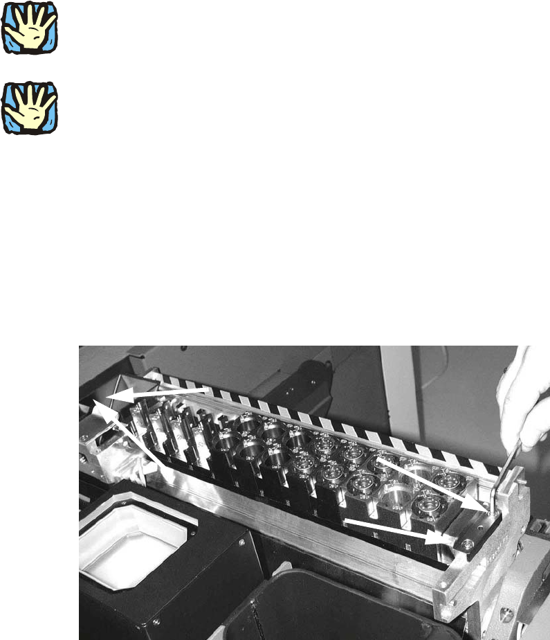
: Loosen the four screws(DIN912 M5x16 - 8.8, item no. 00845044-) on the nozzle changer of
the TwinHead and remove the head.
2 Assembly Instructions - SIPLACE X-Series Head Reconfiguration Kits Head Reconfiguration Kits
07/2010 Edition
164
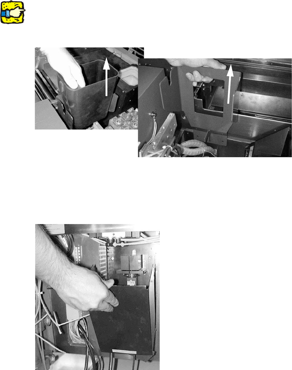
: Remove the large reject bin for the TwinHead.
2
On the subject of the reject bin sensor, also read the assembly instructions for the reject bin sen-
sor, SIPLACE HF series / X series (item no.:00194550-). 2
: Loosen the two screws (DIN912 M6x14 - 8.8, item no. 00095046-01 ) on the TwinHead reject
bin mount and remove the mount.
2
Removing the IC camera 2
: Remove the lighting unit of the IC camera.
: Remove the cover for the IC camera from the base plate by folding it up , and then pulling it up
and out.
2
Head Reconfiguration Kits 2 Assembly Instructions - SIPLACE X-Series Head Reconfiguration Kits
07/2010 Edition
165
: Detach the IC camera cable from the connections on the base plate.
: Push the connecting cable into the machine frame. They are safely stored there.
2
: Replace the two upper screws DIN912 M6 x 35 - 8.8(item no.: 00845062-) with the set screws
DIN913 M6x50 - ST and use them to fix the partition plate for fiducial (item no.: 03022077-)
2
The fiducial plate is very heavy. 2
2
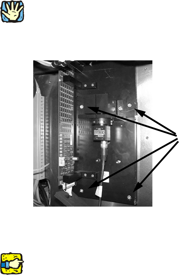
: Loosen the lower two screws (DIN 913 M6x50 - ST, item no.: 03005958-) on the base plate of
the IC camera and remove the camera.
: Loosen the four screws (M6) on the IC camera base plate and remove.
2
Removing the FC camera (if present) 2
: To remove the flip-chip camera, read the
Assembly instructions for the FC camera, digital 16x16 (SST 25) (item no.:00194554-).
2
The fiducial plate for the FC camera is removed in a different way than the IC camera!
It can fall off if it is dismantled in the same way,. 2
If it is not a two-gantry placement area and there is no TwinHead attached to the other gantry, you
can remove the vision controller in the sub- / main distributor. 2
4 screws