M2series_ServiceManual_e.pdf - 第59页
3 Mechanical Section 3-27 ■ Lubrication Po ints for Z-axis Guide / R-axis Splin e Shaft Head U nit Secti o n Z- axi s uni t ( enl ar ged v i ew) R- axi s sp li ne s haf t Z-axis g uide ■ Lubrication Poin ts for S-axis / …
3 Mechanical Section
3-26
NOTE: If too much grease is applied, excess grease may scatter around during machine’s running. Apply proper
amount so that thin coat of grease is made over the surface.
NOTE: If grease is applied on the ball screw surface (out of ditch), the grease will be coming out, not being caught
by ball bearing inside. That may cause insufficient lubrication condition. Then Apply grease onto the ditch
of the ball screw.
■ Lubrication Points for Linear Guide
ACTION:
① Wipe off the dirty grease or adhered grease on the linear guide. Use a nonwoven cloth to wipe, not a
cotton swab or woven cloth that may generate dust or waste threads.
② Push the grease gun to the grease nipple and apply grease in the linear guide nut.
Grease Gun
Grease Nipple
Y-axis Linear Guide
③ Perform “Ageing” in Manual > Warm Up with the less than 20% axis speed for more than 10 minutes.
Speed setting can be done by sliding the “Axis Speed” gauge at [Setting] tab.
④ Then wipe off the pushed-out dirty grease with a nonwoven cloth and apply new grease into the nut
again.
⑤ Remove excessive grease gathered on the nut or both ends of the ball screw with a nonwoven cloth,
and perform “Ageing” by increasing axis speed gradually.
⑥ By Axis command in Manual Menu, move the Head Assy. from an end of axis to the other end for
several times, so that the applied grease is spread over whole of the work range. However, the spread
grease cannot reach the actual end of each axis because of the out of work range of the nut. Then add
some grease there by hand with a nonwoven cloth etc.
NOTE: If a cotton-swab or a woven cloth is used to wipe off the dirty grease, waste threads of cloth may be caught
in the ball screw. Use a nonwoven cloth.
NOTE: Use proper grease for lubrication, specified as our standard. (See the “Specified Lubricants” list at the end
of this chapter.)
NOTE: Remove the excess grease gathered on the nut or both ends of the ball screw by wiping it off with a
nonwoven cloth to avoid grease scattering.
3 Mechanical Section
3-27
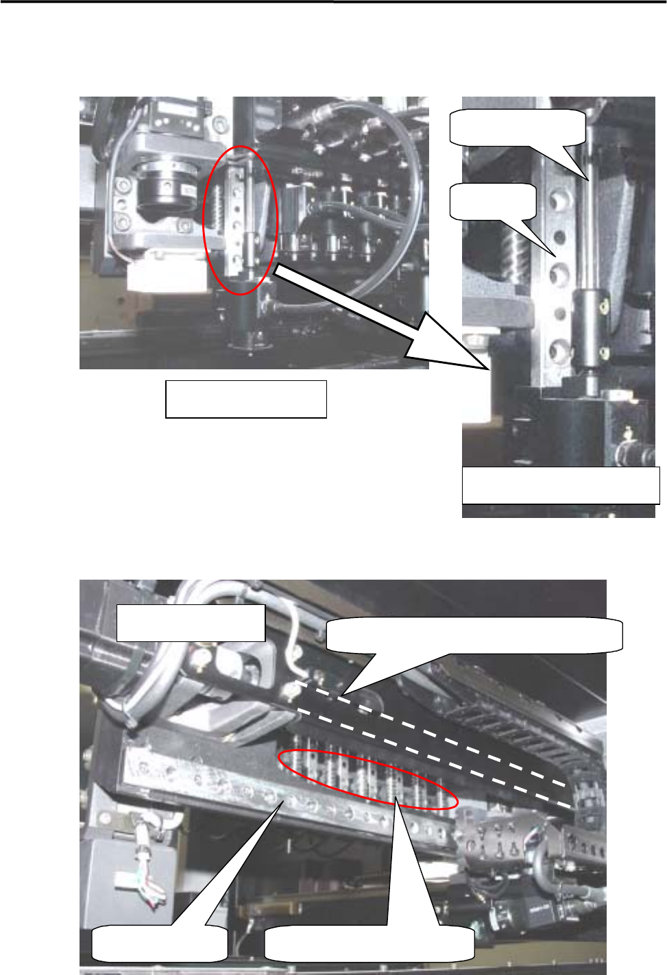
■ Lubrication Points for Z-axis Guide / R-axis Spline Shaft
Head Unit Section
Z-axis unit (enlarged view)
R-axis spline shaft
Z-axis
g
uide
■ Lubrication Points for S-axis / Z-axis Ball Screw
S-axis Linear guide
S-axis ball screw (#1 to #6)
S-axis ball screw (indicated by dotted line)
Rear of head base
3 Mechanical Section
3-28
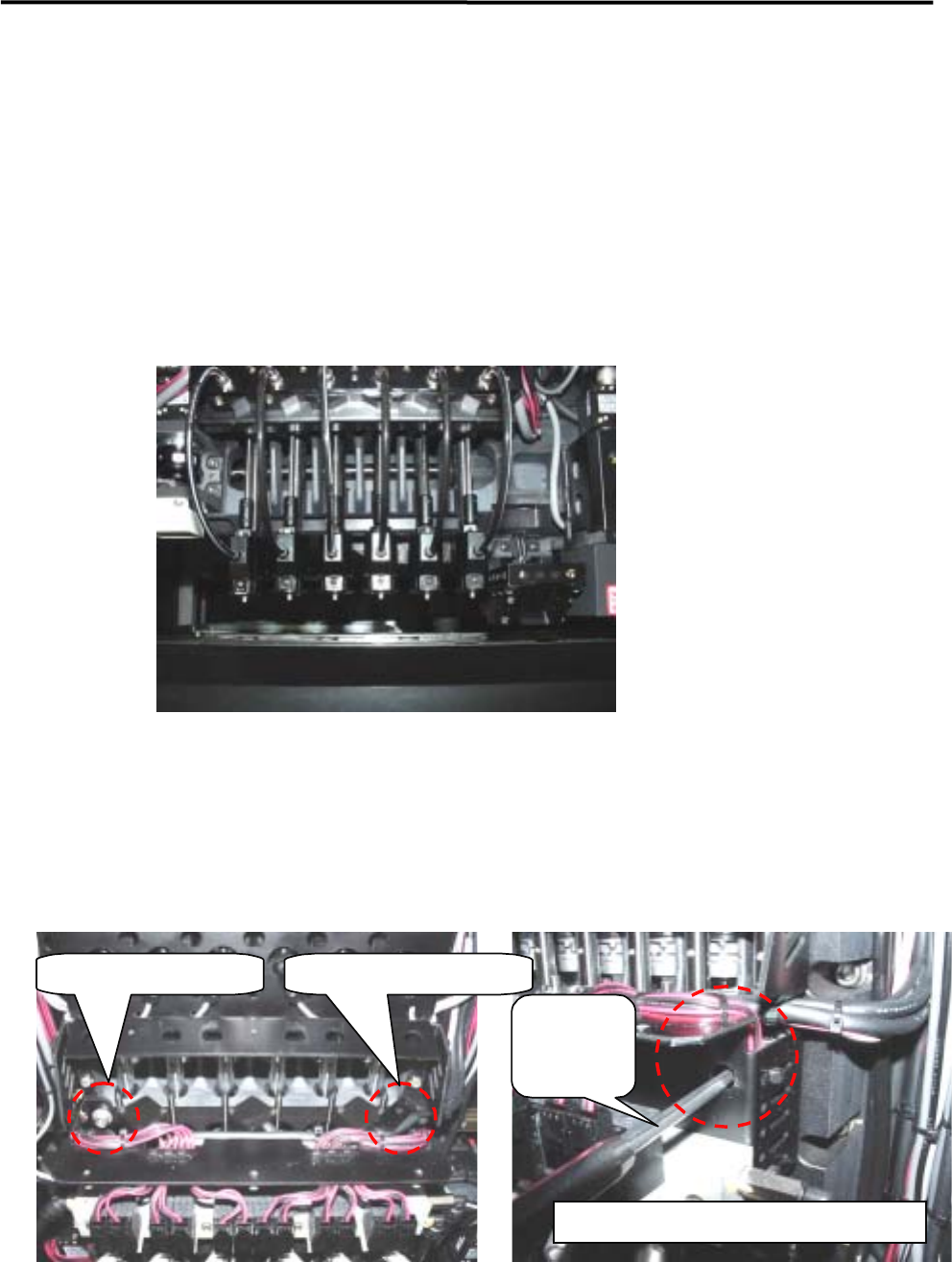
■ Applying Grease to R-axis Gear (R-axis Spline Shaft / Z-axis Ball Screw)
ACTION:
① Select [Manual] to display [Nozzle Info] window. From this window, return all the nozzles to ANC,
and move the head to the center (X-axis) approximately and to the nearest front side (Y-axis) in JOG
mode.
② Remove the head cover unit. (For the method, refer to “Head Cover Unit”.)
③ Turn OFF the main power of the machine.
④ Lower all the heads approximately to the height of the scan camera by hand. (If they are not lowered,
they will cause an obstruction when the head cover base is opened.)
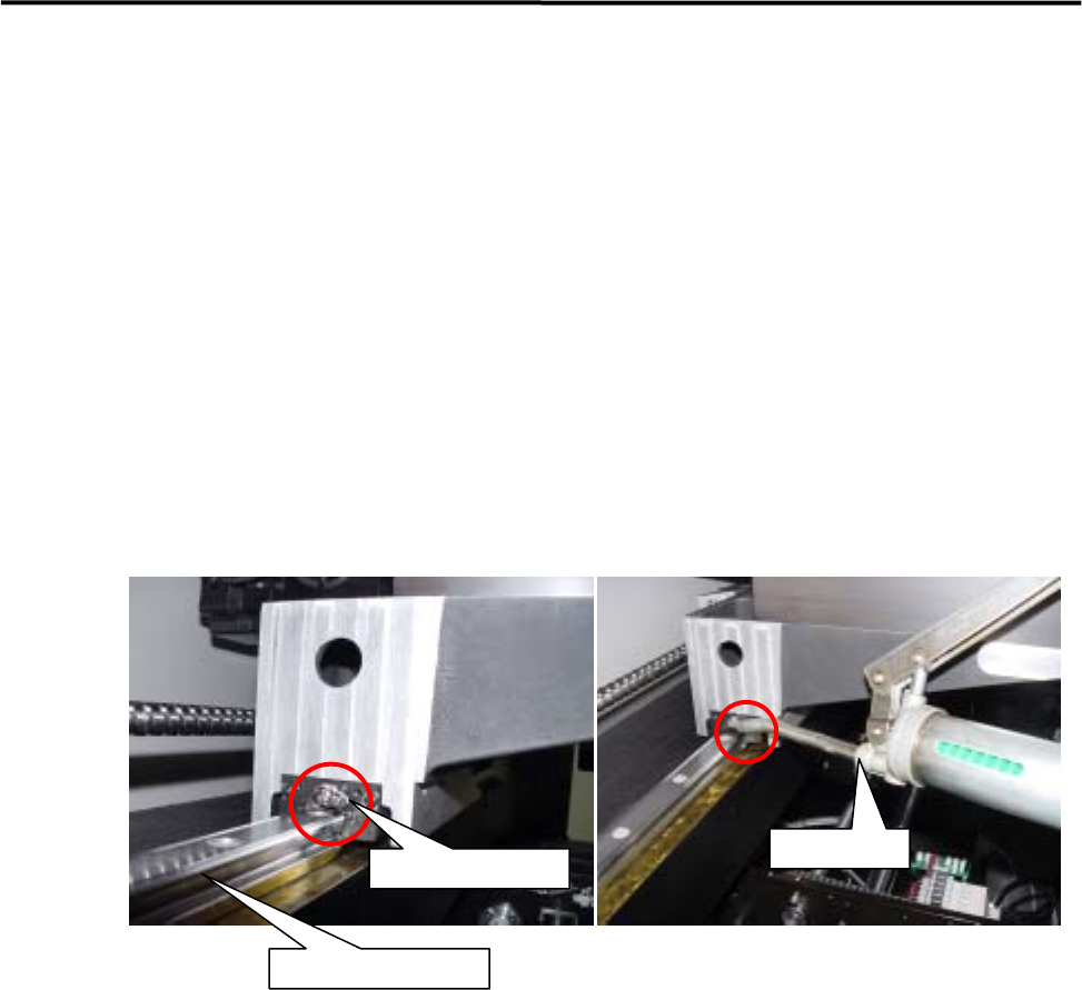
⑤ Loosen the two head cover base fixing screws with a hexagonal wrench.
NOTE: Each fixing screw has an E-ring to prevent the screw from falling. So when loosening/tightening the screws,
turn the E-ring approx. three turns to right and left alternately. If they are turned in one direction only, the
E-ring may deform the head cover base.
Left-side fixing screw Right-side fixing screw
Hexagonal
wrench
Enlarged view of right-side fixing screw