SMTAi Paper_Printing Small Aperture components Final Aug_2_2019.pdf - 第5页
• Stencil: 29 ” X 29 ” frame size, high tensio n, laser cut with Nano-coati ng. Aperture sizes were o ne to one matching the 0.00 5” x 0.006” (0.127 x 0.1524mm) pad size. • Blades: 8” (220 mm ) stainles s steel blades, a…
The recommended sequence is a vacuum/vacuum/dry. The
combined vacuum strokes eliminate any paste pulled from
the aperture and left behind that was the result of the first
pass vacuum. Solvent should be used less frequently as the
purpose of this material is to address the flux that can build
up around the aperture opening. Recommended frequency
for a solvent wipe is every 4-6 wipe cycles. The
recommended solvent stroke sequence is a
solvent/vacuum/dry where a solvent application always
begins the sequence. Consult your paste manufacturer for
recommended solvents to ensure that the solvent used is
compatible with the paste flux. A quality paper should be
used as Type 6 paste can be difficult to clean, where
economy paper can have issues with retaining the solder
balls and contamination issues could result. [1]
The Printer:
The printer plays the major role in the success of printing
008004” (0201mm) components. It’s recommended prior to
printing micro apertures to make sure all preventive
maintenance and calibrations are up to date. The alignment
capability of the machine is vital for dealing with small
pads. Advancements in machine vision repeatability and
accuracy has kept pace with the introduction of micro-
components. However, if your machine was designed back
in the 1990’s, then it most likely will not have the accuracy
resolution to handle these component challenges. Testing
the machines vision alignment capability prior to developing
the process is recommended so that with the machine
verified, issues with alignment can be isolated and solved
more quickly. This can be done using a print verification
process, using embedded machine software that measures
paste deposits for accuracy and repeatability, the results will
determine if a vision calibration is warranted. Another key
calibration on the printer that is often overlooked is the table
leveling to the stencil rails. Since gasketing is paramount
when printing micro apertures, this calibration takes into
consideration the four corners of the table as it applies to the
stencil rails for proper seating between the PCB and stencil.
This calibration is overlooked as it was most likely done
when the machine was built by the manufacturer and never
addressed again after installation. One of the issues with
doing this calibration was the difficulty with the procedure
used. A feeler gage is employed to measure the distance
from the table to the bottom of the adjacent stencil rail. In
order to measure the four points, the gage is moved from
corner to corner repeatability to dial the distance to within
specifications. This process requires the machine to be down
significantly often taking hours to complete. A new tool
developed by MPM addresses this issue by adjusting all
four corners simultaneously. To date, specifications for table
to stencil leveling has been in the range of +/- 0.004”
(0.1016mm). However, studies have shown best results are
achieved when the specification is dropped to +/- 0.001”
(0.0254mm). To eliminate any tolerance issues between the
table and the tooling plate, the plate can be used as a
reference during this calibration. This specification can be
achieved using this calibration tool and has played a
contributing role in successfully printing micro apertures.
The time to complete this calibration has been reduced to
roughly 1 hour. Lastly, the printing machine should be
completely inspected for cleanliness and clean any paste
debris found. Root cause for many issues can be traced to
random paste deposits or residual paste that builds up over
time.
DESIGN OF EXPERIMENT:
Print Test for 008004 (0201mm)
Overview:
To demonstrate micro-component printing capability, with a
focus on the 008004” (0201mm) component using the new
SMTA miniaturization test vehicle. Using best practices
described above, examine the results to determine Cp, CpK,
Pp and PpK results. The goal is to achieve a process
capability, Cp, that is equal to or greater than 2.0 as well as
a CpK greater than 2.0 that demonstrates that the process in
within Six Sigma quality levels. The Pp and PpK numbers
will be examined to see how well the process is centered
with a goal of equal to or greater than 1.667. The test will
use the Edison platform to perform the printing using a
standard configuration. A description of the DOE and
details on the machine, materials and process used as well as
an examination of the results is as follows:
Design of Experiment:
The test consisted of printing a total of 24 PCBs with the
first 4 PCBs to be used as kneed boards to normalize the
process and get the solder paste to a working viscosity. A
wipe will be performed after each print to eliminate any
noise from the data. The remaining 20 PCBs will be
inspected by a Parmi SPI machine with the corresponding
data analyzed through a on board SPC package. Process
data for volume and height for the 008004” (0201mm)
components will then be gathered and displayed and studied
to determine the process capability of printing 008004”
(0201mm) components. All equipment used was recertified
prior to this test being performed.
Materials:
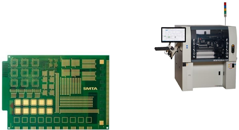
• Printed Circuit Board (PCB): The PCB used for
this experiment is the new SMTA miniaturization
test vehicle. (Figure 2) The board dimensions are
8.0” (203mm) in X and 5.5” (139.7mm) in Y with
a thickness of 0.062” (1.57mm). There are
approximately 400 pads per board with 200
positioned at 0 degrees and 200 pads positioned at
90 degrees. The 008004” (0201mm) pads are
0.005” x 0.006” (0.127 x 0.1524mm) with an air
gap between pads of 0.0047” (1.1938mm) and a
component pitch of 0.00126” (0.032mm)
• Stencil: 29” X 29” frame size, high tension, laser
cut with Nano-coating. Aperture sizes were one to
one matching the 0.005” x 0.006” (0.127 x
0.1524mm) pad size.
• Blades: 8” (220mm) stainless steel blades, at 55-
degree attack angle
• Paste: Type 6 - SAC305 No-clean flux
• Tooling: Dedicated work holder with vacuum –
custom made to SMTA PCB.
Figure 2: SMT Miniaturization Test Vehicle
Printing machine: the Edison platform was used for this
test. (Figure 3) The Edison was specifically designed for
small to medium sized boards and the printing of micro
sized components. The machine vision specifications of a
+/- 0.0003” (8µ) repeatability with a Cp of 2.0 @ six sigma
and a wet print repeatability of 0.0006” (15µ) with a Cp of
@ six sigma. The thin vision camera design reduces the
distance the z-axis must travel when loading or releasing a
PCB. The system uses a X/Y/Y alignment where the
alignment motors have been moved further apart for better
resolution. The Z-axis is tuned to the center of the board
where when the Z-axes is raised, the PCB and the whole the
rail assembly is decoupled from the table to eliminate any
stack up intolerances. This ensures that proper gasketing is
done and a clean release from the stencil. The stationary
wiper is positioned in the front of the machine and the
stencil is presented to the wiper via a shuttle eliminating any
contamination in the print chamber. The print head uses a
single load cell to monitor both squeegees to prevent print
direction variation. All calibrations were performed on this
machine and was validated using CeTaQ testing procedures.
Solder Paste Inspection: For solder paste inspection we
used the Pari Sigma X that was retrofitted with the new
high-resolution inspection head. Standard SPI inspection
heads do not have the resolution to handle micro component
paste deposits. The speed of the scan is slowed from a
100cm/sec to 60 cm/sec to facilitate the micro deposits. The
system uses a dual laser optical triangulation and has
specification of height accuracy of 2um with a height and
volume repeatability of 1%. A gage R+R test was performed
prior to performing testing.
Figure 3: MPM Edison Stencil Printer
Machine Parameters:
• Squeegee force: 14 lbs. (1.35 kg)
• Squeegee Speed: 1.5 in/sec (38mm/sec)
• Slow Release Distance/Speed: Distance = 0.100
(2.54mm) Speed = 0.100 (2.54mm)
• Wipe Frequency; Every PCB
• Wipe Sequence: Vacuum / Vacuum / Dry
• Board clamping: Vacuum and side snugging
Results:
Paste Volume and Height for Pads 0 degrees – refer to
(Figure 4) for volume measurements and (Figure 5) for
height measurements. The limits for volume were set to 50
% for the lower limit and the upper limit was set to 170%.
The distribution curve is centered and shows the average
paste volume to be 114.05%, the low end of the volume was
88.74% and the upper volume found was at 139.37. The Cp
was calculated at 2.37 and the CpK was calculated at 2.21.
The Pp was 2.37 and the PpK was 2.21. The height limits
were set to 50% for the lower limit and 150% for the upper
limit. The distribution curve is shifted towards the higher
end with an average height at 114% with a lower end at
99% and an upper reading of 129%. The Cp was recorded at
3.2 with a CpK of 2.32. The Pp was calculated at 3.28 and
PpK at 2.32.
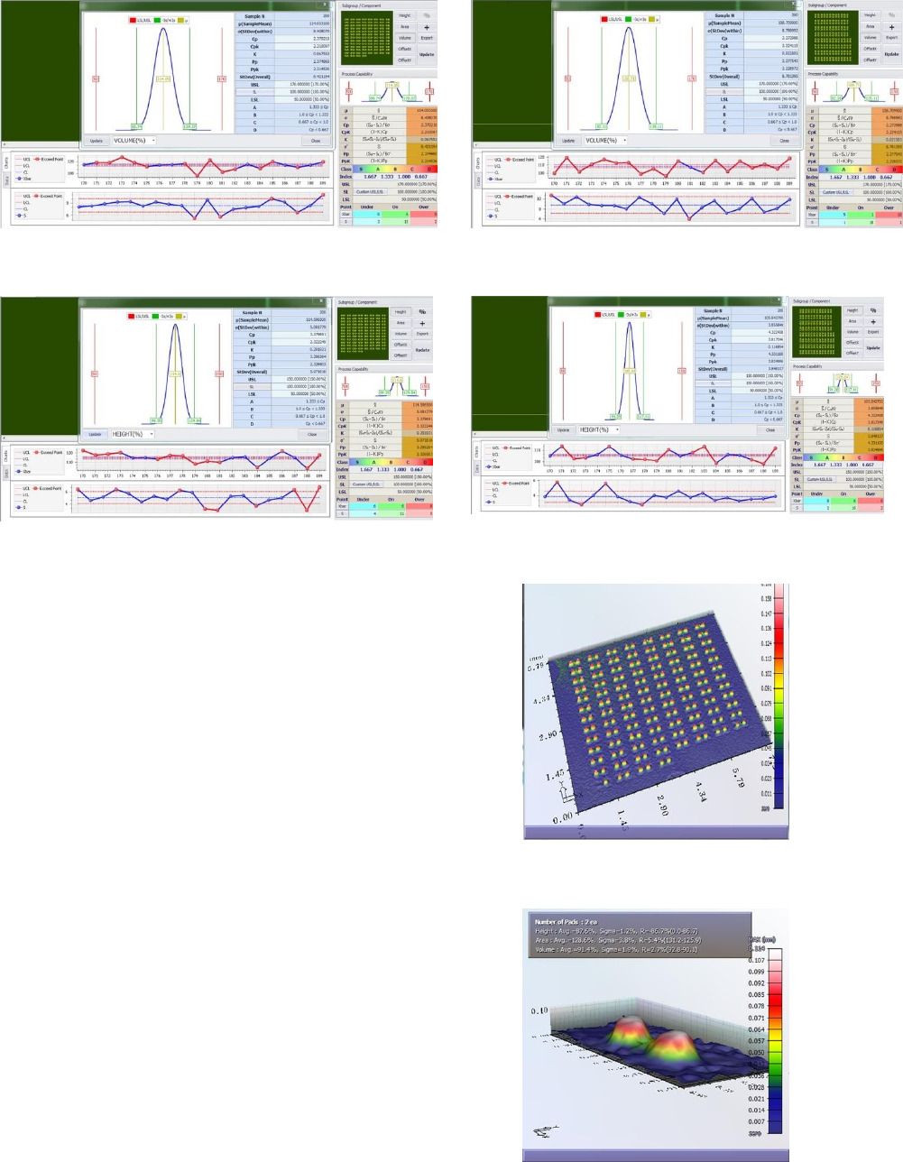
Figure 4: Volume Results 0-Degrees 008004” (0201mm)
Figure 5: Height Results 0-Degrees 008004” (0201mm)
The results show that volume was treading slightly higher
but consistent. The Height was higher than desired but the
distribution is tighter, which was reflected in the higher Cp
number.
Paste Volume and Height for Pads 90 degrees – refer to
(Figure 6) for volume measurements and (Figure 7) for
height measurements. The limits for volume were set to 50
% for the lower limit and the upper limit was set to 170%.
The distribution curve is centered and shows the average
paste volume to be 108.71% where the low end of the
volume was 82.31% and the upper volume was at 135.11%.
The Cp was calculated at 2.27 and the CpK was calculated
at 2.24. The Pp was 2.27 and the PpK was 2.28. The height
limits were set to 50% for the lower limit and 150% for the
upper limit. The distribution curve is centered with an
average height at 105.84% with the lower end at 94% and
an upper reading of 117%. The Cp was recorded at 4.22
with a CpK of 3.81. The Pp was calculated at 4.31 and PpK
at 3.82.
Figure 6: Volume Results 90-Degrees 008004” (0201mm)
Figure 7: Height Results 90-Degrees 008004” (0201mm)
Figure 8: Overview of paste deposits 008004” (0201mm)
Figures 9: Individual Paste Deposits 008004” (0201mm)