SMTAi Paper_Printing Small Aperture components Final Aug_2_2019.pdf - 第6页
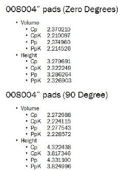
Figure 4: Volu m e Results 0 - Degrees 008 004” (0201mm) Figure 5: Heig ht Results 0- Degrees 008 004” (0201mm) The results show that vol ume was treading slightl y higher but consistent. T he Height was higher t han des…
• Stencil: 29” X 29” frame size, high tension, laser
cut with Nano-coating. Aperture sizes were one to
one matching the 0.005” x 0.006” (0.127 x
0.1524mm) pad size.
• Blades: 8” (220mm) stainless steel blades, at 55-
degree attack angle
• Paste: Type 6 - SAC305 No-clean flux
• Tooling: Dedicated work holder with vacuum –
custom made to SMTA PCB.
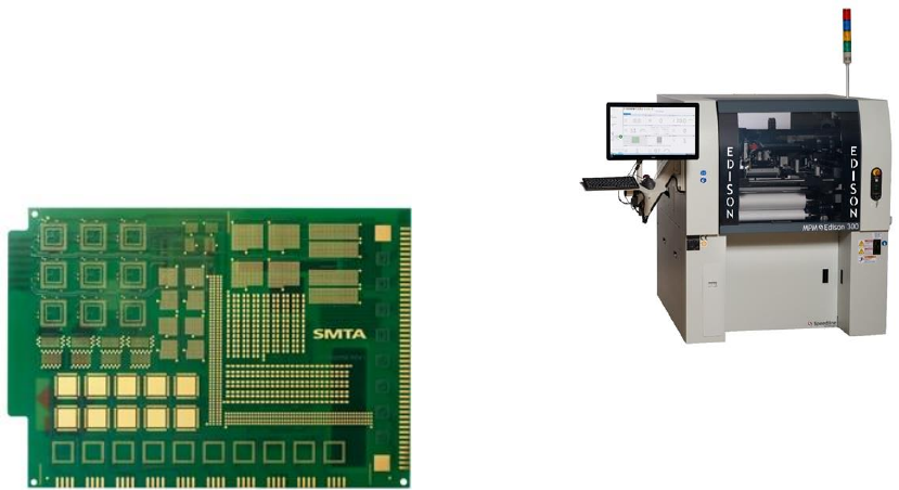
Figure 2: SMT Miniaturization Test Vehicle
Printing machine: the Edison platform was used for this
test. (Figure 3) The Edison was specifically designed for
small to medium sized boards and the printing of micro
sized components. The machine vision specifications of a
+/- 0.0003” (8µ) repeatability with a Cp of 2.0 @ six sigma
and a wet print repeatability of 0.0006” (15µ) with a Cp of
@ six sigma. The thin vision camera design reduces the
distance the z-axis must travel when loading or releasing a
PCB. The system uses a X/Y/Y alignment where the
alignment motors have been moved further apart for better
resolution. The Z-axis is tuned to the center of the board
where when the Z-axes is raised, the PCB and the whole the
rail assembly is decoupled from the table to eliminate any
stack up intolerances. This ensures that proper gasketing is
done and a clean release from the stencil. The stationary
wiper is positioned in the front of the machine and the
stencil is presented to the wiper via a shuttle eliminating any
contamination in the print chamber. The print head uses a
single load cell to monitor both squeegees to prevent print
direction variation. All calibrations were performed on this
machine and was validated using CeTaQ testing procedures.
Solder Paste Inspection: For solder paste inspection we
used the Pari Sigma X that was retrofitted with the new
high-resolution inspection head. Standard SPI inspection
heads do not have the resolution to handle micro component
paste deposits. The speed of the scan is slowed from a
100cm/sec to 60 cm/sec to facilitate the micro deposits. The
system uses a dual laser optical triangulation and has
specification of height accuracy of 2um with a height and
volume repeatability of 1%. A gage R+R test was performed
prior to performing testing.
Figure 3: MPM Edison Stencil Printer
Machine Parameters:
• Squeegee force: 14 lbs. (1.35 kg)
• Squeegee Speed: 1.5 in/sec (38mm/sec)
• Slow Release Distance/Speed: Distance = 0.100
(2.54mm) Speed = 0.100 (2.54mm)
• Wipe Frequency; Every PCB
• Wipe Sequence: Vacuum / Vacuum / Dry
• Board clamping: Vacuum and side snugging
Results:
Paste Volume and Height for Pads 0 degrees – refer to
(Figure 4) for volume measurements and (Figure 5) for
height measurements. The limits for volume were set to 50
% for the lower limit and the upper limit was set to 170%.
The distribution curve is centered and shows the average
paste volume to be 114.05%, the low end of the volume was
88.74% and the upper volume found was at 139.37. The Cp
was calculated at 2.37 and the CpK was calculated at 2.21.
The Pp was 2.37 and the PpK was 2.21. The height limits
were set to 50% for the lower limit and 150% for the upper
limit. The distribution curve is shifted towards the higher
end with an average height at 114% with a lower end at
99% and an upper reading of 129%. The Cp was recorded at
3.2 with a CpK of 2.32. The Pp was calculated at 3.28 and
PpK at 2.32.
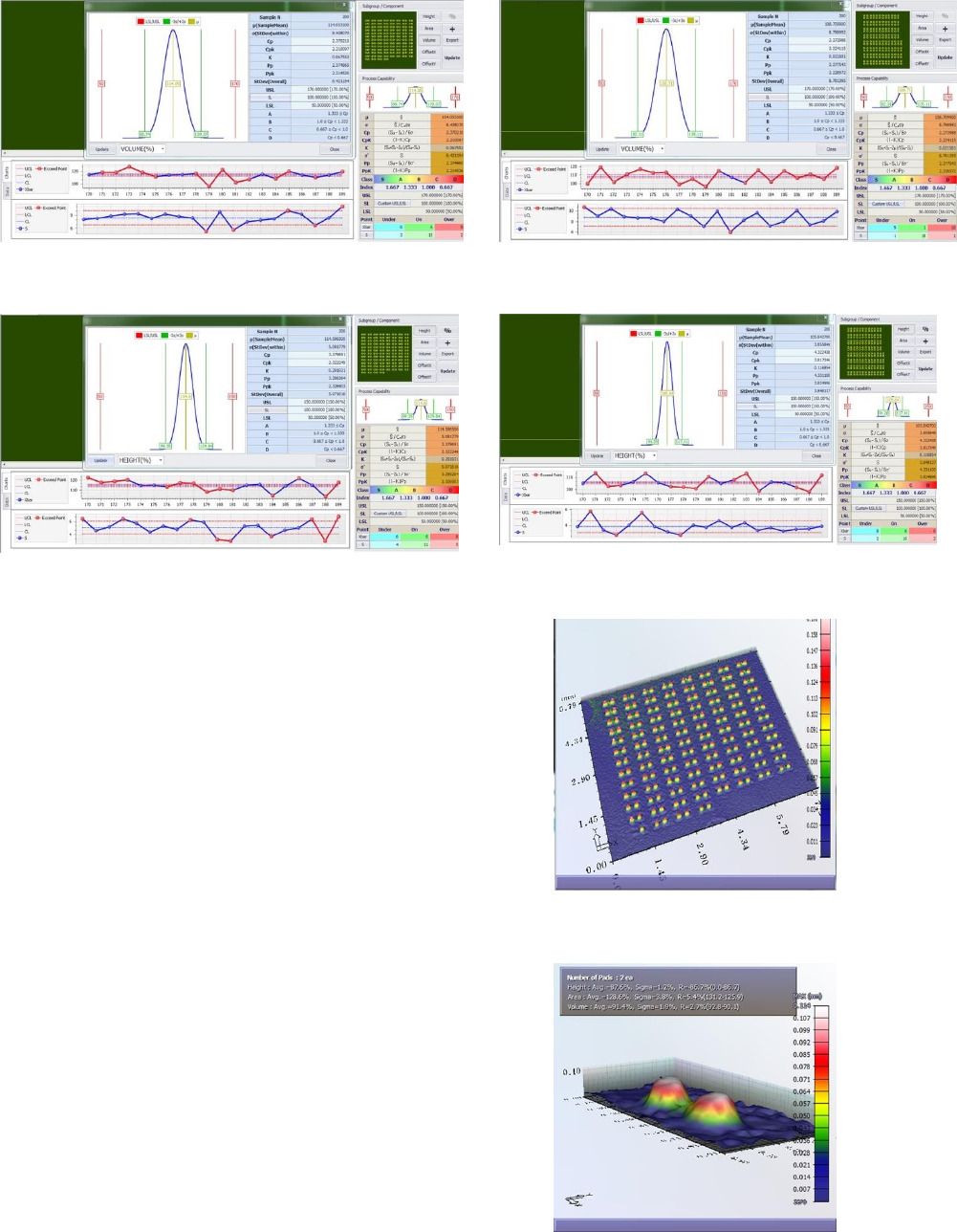
Figure 4: Volume Results 0-Degrees 008004” (0201mm)
Figure 5: Height Results 0-Degrees 008004” (0201mm)
The results show that volume was treading slightly higher
but consistent. The Height was higher than desired but the
distribution is tighter, which was reflected in the higher Cp
number.
Paste Volume and Height for Pads 90 degrees – refer to
(Figure 6) for volume measurements and (Figure 7) for
height measurements. The limits for volume were set to 50
% for the lower limit and the upper limit was set to 170%.
The distribution curve is centered and shows the average
paste volume to be 108.71% where the low end of the
volume was 82.31% and the upper volume was at 135.11%.
The Cp was calculated at 2.27 and the CpK was calculated
at 2.24. The Pp was 2.27 and the PpK was 2.28. The height
limits were set to 50% for the lower limit and 150% for the
upper limit. The distribution curve is centered with an
average height at 105.84% with the lower end at 94% and
an upper reading of 117%. The Cp was recorded at 4.22
with a CpK of 3.81. The Pp was calculated at 4.31 and PpK
at 3.82.
Figure 6: Volume Results 90-Degrees 008004” (0201mm)
Figure 7: Height Results 90-Degrees 008004” (0201mm)
Figure 8: Overview of paste deposits 008004” (0201mm)
Figures 9: Individual Paste Deposits 008004” (0201mm)
The results show a tighter more centered curve for 90
degrees for both volume and height. The volume is shifted
slightly towards the center, which is closer to the preferred
position. The height for the 90-degree components shows a
very tight curve with a Cp of 4.22, which is the most
substantial improvement from the 0-degree components.
closer to the preferred position. (Figure 10) shows a
summary of the results.
Figure 10: Test Results Summary
CONCLUSION:
The results of the print test show that 008004” (0201mm)
components can be repeatably printed and can be done
where the process window is twice the capability. The
results also show that pads that are oriented at 90-degrees
gave the best results, however, the 0-degrees orientation was
well within specification. The ability to print micro sized
components is obtainable when each of the elements are
addressed with the machine, the materials and the process
working together. No individual aspect outweighs the other
where working together, the wheels of the process turn in
sync in order to achieve the desired results.
Future Work: Further investigation needs to be done, to see
the effects of printing 008004” (0201mm) components with
different powder sizes and understanding the associated
costs versus capability, compared to the type 6 powder.
Another test would involve comparing the results of
squeegee blades vs enclosed print head, to see if there are
any advantages between these two applications methods.
REFERENCES:
[1] Study completed Shea Engineering Services