CUKYX-193-5100_G5S2.pdf - 第174页
193-5100 CUKYX 2.44 I/O 板 _U08 的连接电路 1 4-59 2.44 I/O 板 _U08 的连接电路 1 IO PCB U08 STL T_CNVR 1 2 X1 1 2 X2 3 4 CN1 X0801 RX+ X08X1 X08X2 RX- TX+ SG SG TX- SG SG FG 1 2 3 4 5 6 7 8 CN2 X0802 TX+ TX- RX+ SG SG RX- SG SG FG 1 …
193-5100
CUKYX
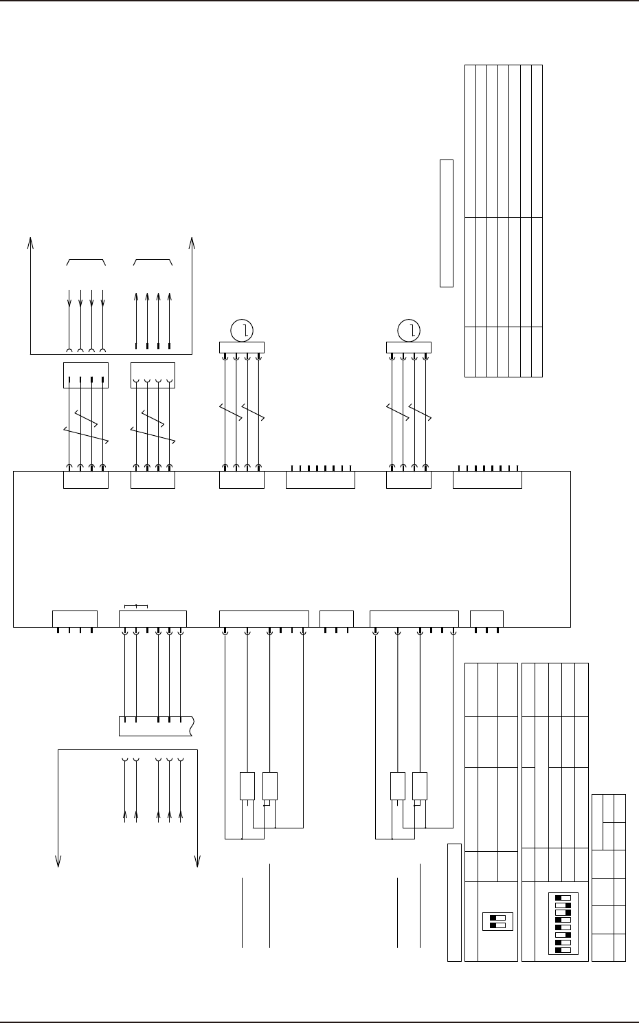
2.43 A11_ 马达驱动器的连接电路
4-58
2.43 A11_ 马达驱动器的连接电路
NA BL Motor origin
1
2
3
4
5
6
NA BR Motor origin
MGND
MGND
CGND
MV+
MV+
CV+
2
4
3
1
E/C A+
E+5V
5
7
6
8
E/C A-
E/C B+
E/C B-
E/C Z+
E/C Z-
EGND
2
3
1 BRK+
BRK-
N.C.
M
2
4
3
1
/B
/A
B
A
2
3
1
4
NA_BL Motor
M45
CN1
X1101
CN3
2
4
3
1
E/C A+
E+5V
5
7
6
8
E/C A-
E/C B+
E/C B-
E/C Z+
E/C Z-
EGND
M
2
4
3
1
/B
/A
B
A
2
3
1
4
NA_BR Motor
M46
CN5
X1105
CN7
1 SEN+
CN4
2 SEN1
3 SEN2
5 SEN4
6 COM
4 SEN3
X1104
CN2
2
3
1 STP+
STP-
ALM+
CN9
4 ALM-
:A4
:A5
:B4
:B5
:B1
10
10
48D
48D
24A6
XCV-R
CN10
X1110
2
4
3
N1
2
4
3
N2
GND(SG)
COM B
+V
COM A
COM B
+V
COM A
XN1
1
1
GND(SG)
XN2
Stepping Motor Driver
A11
G5S Platform
XCV-R
:2
:3
:1
:4
from U85-2CH
[F-/03/7C]
COM A
COM B
10
24A6
to A63F-CN12
[DC/02/2B]
COM A
COM B
10
24A6
G5S Platform
XAE2CH
XAE-CT
XAE
:2
:3
:1
:4
XAE-CT
Servo OFF
MV+ Motor power indication
Control power indication
Alarm indication
Remarks
CV+
ALM
LED Name
Lit on 48D supply
Lit on 26A6 supply
Normal lighting / abnormal lights off
BUSY1 Axis.1 Operation indication
OP(unused)
BUSY2
CM
M45 lit during operation
Always on
Axis.2 Operation indication M46 lit during operation
(Axis.1)
(Axis.2)
B11104
OUT
-
L
+
B21104
OUT
-
L
+
24A6
10
2
3
1 BRK+
BRK-
N.C.
1 SEN+
CN4
2 SEN1
3 SEN2
5 SEN4
6 COM
4 SEN3
X1104
CN2
B11108
OUT
-
L
+
B21108
OUT
-
L
+
24A6
10
Axis.1
Address
Axis.2
SW2-1
SW2-2 SW2-3 SW2-4
8 9OFF OFFONOFF
NA BL Motor
out of step detection
NA BR Motor
out of step detection
A11 Configuration
1
ON
2
OFF
AE-LINK Termination
NO.
Setting contents Configuration Remarks
SW1
1
OFF
AE-LINK Termination
2
1
ON
2 3 4
5 6 7 8
6
7
STP(Emergency stop)
1~4
Please refer to the table below
OFF
ON
NO.
Setting contents Configuration Remarks
Invalid
SW2
5,8
unused
Communication speed setting
ON
307.2Kbps
A11 LED Description
KYX-000-CC-040.ai
193-5100
CUKYX
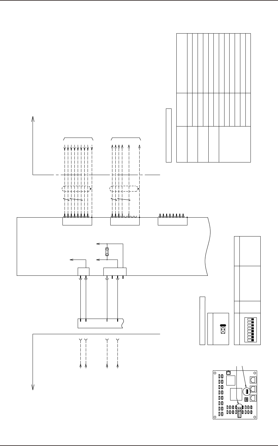
2.44 I/O 板 _U08 的连接电路 1
4-59
2.44 I/O 板 _U08 的连接电路 1
IO PCB
U08
STLT_CNVR
1
2
X1
1
2
X2
3
4
CN1
X0801
RX+
X08X1
X08X2
RX-
TX+
SG
SG
TX-
SG
SG
FG
1
2
3
4
5
6
7
8
CN2
X0802
TX+
TX-
RX+
SG
SG
RX-
SG
SG
FG
1
2
3
4
5
6
7
8
CN3
SG
SG
SG
SG
FG
1
2
3
4
5
6
7
8
TX+
TX-
RX+
RX-
from U85-T(X85T)
[F-/03/7B]
to X30C1-B
[B-/06/1D]
:A1
10
:B1
24A6
:A2
10
:B2
24A3
XCV-L
G5S Platform G5S Platform
ON
54321 67 8
SW1
U08 Layout
CN39
CN38
CN41
CN40
CN43
CN42
CN45
CN44
CN31
CN30
CN33
CN32
CN34
CN35
CN37
CN36
CN11 CN10
CN12
CN13
CN14
CN15
CN16
CN17
CN18
CN19
CN20
CN21
CN22
CN23
CN24
CN25
JP1
JP1
CN1
CN2 CN3
Communication
Communication LED1~8
LED9
LED1~8
LED9
Lights off
Lights on
Sequential lighting
Lights off
ID set complete
LED1~8
LED9
ID value
Lights off
LED1
LED2
Lighting up:Manchester error
Lighting up:Parity error
LED3
LED4
Lighting up:Link pulse error
Lighting up:CRC error
LED5~8
LED9
Lights off:unused
Flashing
Error occurred
U08 state LED1~8 (Yellow) LED status
LED9 (Red)
1
ON
2 3 4
5 6 7 8
OFF
1~8 unused
NO. Setting contents ConfigurationSW1
JP1
Close
A B
JP1
C
U08 Configuration
U08 LED Description
connection
not connected
KYX-000-CC-041
193-5100
CUKYX
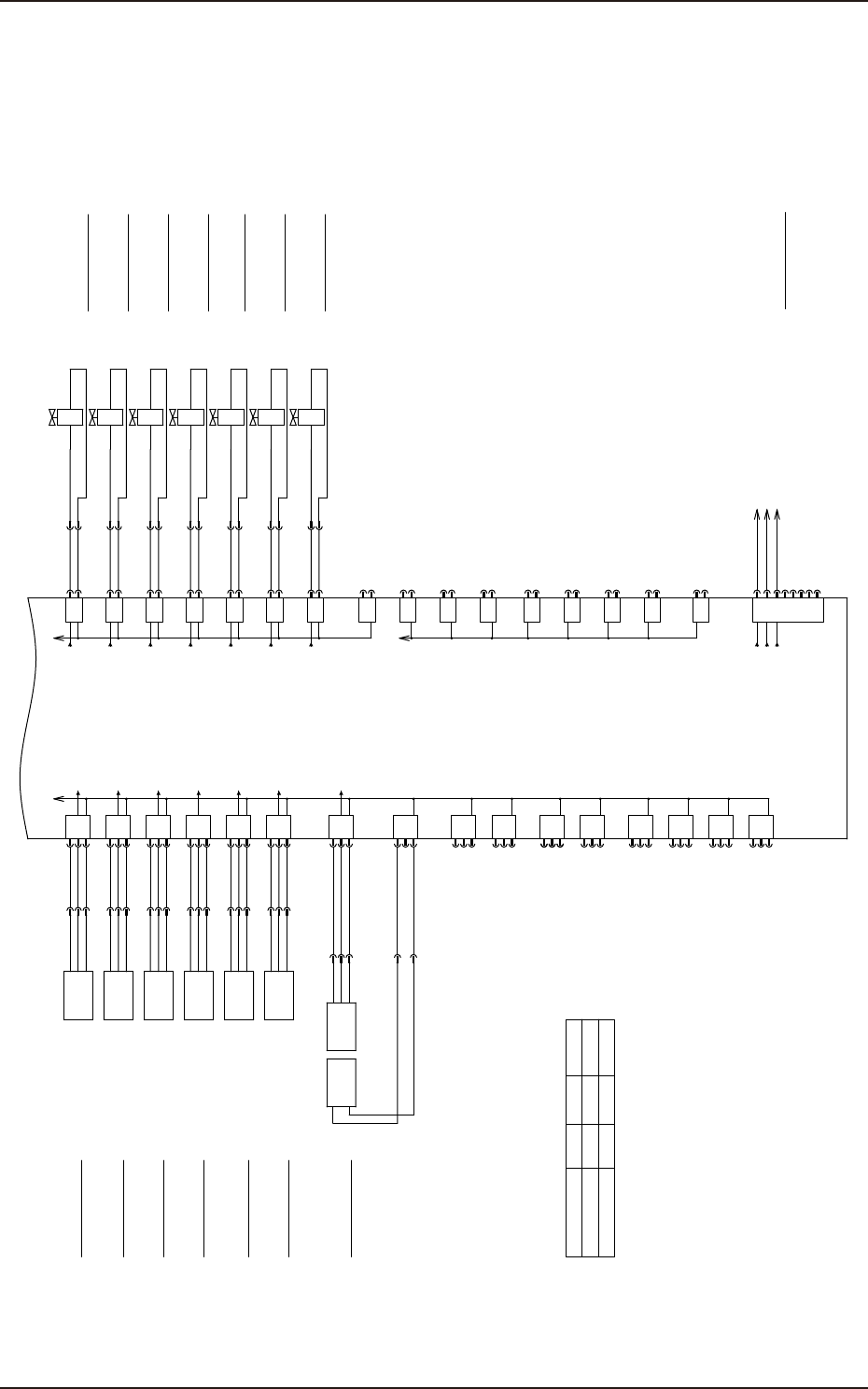
2.45 I/O 板 _U08 的连接电路 2
4-60
2.45 I/O 板 _U08 的连接电路 2
X0836
X0831
X0830
X0812
X0813
X0815
X0814
B0830
B0830
:3
+
OUT
-
:2
:1
B0836
+
OUT
-
B0836T
-
+
B0836
:3
:2
:1
Movable chute
Backup Pin Sensor
X0832
X0833
B0831
:6
+
OUT
-
:5
:4
B0832
B0832
:3
+
OUT
-
:2
:1
B0833
+
OUT
-
Y0812
:5
:6
BK R
Left board stopper lifting valve
Y0813
:7
:8
BK R
Y0810
:1
:2
X0810
BK R
Y0811
:3
:4
BK R
Y0814
:9
:10
BK R
IN OUT
CN10
CN11
CN12
CN13
CN14
CN15
CN16
CN17
CN18
CN19
CN20
1
2
3
3
2
1
3
2
1
3
2
1
3
2
1
3
2
1
1
2
3
1
2
3
1
2
3
1
2
3
3
2
1
2
1
CN40
CN39
CN38
CN37
CN36
CN35
CN34
CN33
CN32
CN31
CN30
1
2
1
2
1
2
1
2
1
2
1
2
1
2
1
2
1
2
1
2
IO PCB
U08
Right board stopper lifting valve
Y0815
:11
:12
BK R
X0810
X0811
X0816
X0834
X0835
B0834
B0834
:3
+
OUT
-
:2
:1
B0835
+
OUT
-
Long board stopper lifting valve
Y0816
:1
:2
X0816
BK R
CN21
CN22
CN23
CN25
1
2
3
3
2
1
3
2
1
3
2
1
3
2
1
CN45
CN43
CN42
CN41
CN24
1
2
1
2
1
2
1
2
1
2
CN44
:1
:2
B0836T
BL
BK
BR
BL
BK
BR
BL
BK
BR
BL
BK
BR
BL
BK
BR
BL
BK
BR
BL
BK
BR
BL
BR
STLT_CNVR
Note
X0837
:6
:5
:4
:6
:5
:4
B0830
B0832
B0834
X0810
X0810
X0810
X0810
X0810
CN27
1
2
X0827
3
4
5
6
7
8
B11003 :4
B21003 :4
B31003 :4
Substrate stop sensor left Remote
Board stop sensor Right remote
Long board stop(OP) sensor remote
1. The board stopper name
differs depending on the flow direction.
Please refer to the table below.
stopper1 stopper2 stopper3
L to R
R to L
Left
Left
Right Long
Right Long
Note 1
[N-/03/2C]
Flow direction
B
AC
Di00
Do00
Di01
Di02
Di03
Di04
Di05
Di06
Do01
Do02
Do03
Do04
Do05
Do06
Do10
Do09
Do08
Board stopper 1
lower limit detection
Board stopper 1
upper limit detection
Board stopper 2
lower limit detection
Board stopper 2
upper limit detection
Board stopper 3
lower limit detection
Board stopper 3
upper limit detection
Z Clamp Left
Cylinder Valve Descent
Z Clamp Left
Cylinder Valve Rising
Z Clamp Right
Cylinder Valve Descent
Z Clamp Right
Cylinder Valve Rising
KYX-000-CC-042