ASM-SX-V3-设备性能参数-DMS.pdf - 第42页
42 ASM Software Products Overview Workflows ASM Software Product St andar d Op tion Planning ASM pr oductio n plan ner Fully automatic product grouping and optimization by taking del iv- ery deadlines into account X SIPL…
41
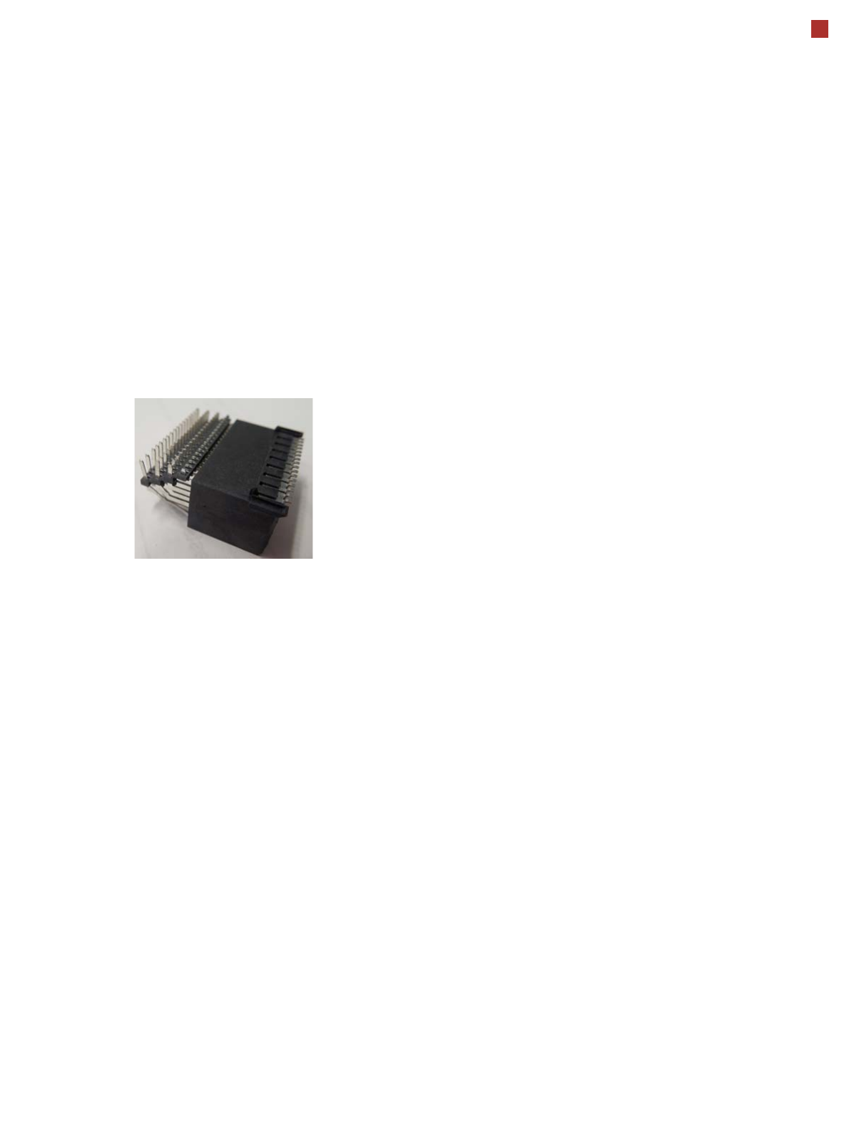
OSC package
The licensed OSC package
contains functions for simpli-
fied placement of odd
shaped components (OSC),
such as connectors or sock-
ets.
The license is activated via
SIPLACE PRO.
For detailed information,
refer to the OSC package
user guide, item number
[00198374-xx].
The following functions are
contained in the OSC pack-
age:
OSC measurement options
• Customized odd shaped
component
This enables the user to
describe any abstract pat-
tern on a component e.g.
connection leads of a tri-
angular shape. This pat-
tern can then be easily
created and edited at the
station, using the wizard
function.
• Stereo measurement
Stereo measurement
means that two images
are taken of each compo-
nent, from different direc-
tions, using a stationary
camera. These images
are overlapped to show
connectors, pins etc. in 3D
to support easy and pre-
cise evaluation of struc-
tures which, due to color,
shading or background
structures, are difficult to
recognize in conventional
2D measurement.
• Special position evalua-
tion
This function supports
separate definition of posi-
tion-determining features
(x,y, angle) independent
of the features for good-
bad recognition.
Placement of snap-in com-
ponents
This function monitors
whether snap-in components
engage in the board prop-
erly, during automatic place-
ment.
Pin in paste height check
This option extends the
"snap-in" function for CPP
and Twin heads.
Automatic calculation of
optimum acceleration
This function enables the
user to automatically calcu-
late the optimum accelera-
tion of individual axes for a
component at the station.
The acceleration values
found can then be checked in
an additional test run and
sent back to the program-
ming system if successful.
Placement of very high
components
In special application cases
the software can place a very
high component with auto-
matic collision prevention.
Additional force levels for
TH and CPP head
•30 N for TH
• 100 N for VHF TH
• 15 N for CPP
15.5 mm high components with CPP restrictions
• The maximum height of 15.5 mm can only be reached if the
PCB warpage upwards is 0 mm (setting in SIPLACE Pro).
• NO SIPLACE TwinStar permitted anywhere in the line.
• If there are two SIPLACE MultiStars (CPP) in the same
placement area, only one CPP can place components up to
15.5 mm.

42
ASM Software Products
Overview
Workflows ASM Software Product Standard Option
Planning
ASM production planner
Fully automatic product grouping and optimization by taking deliv-
ery deadlines into account
X
SIPLACE SiCluster Professional / SiCluster Multiline
Fully automatic product grouping
X
Virtual production
SIPLACE Pro
One application for all programming tasks
X
SIPLACE LED Pairing
Simple placement of LEDs with multiple classes
X
Process optimization
ASM DFM HealthCheck
Automatic determination of optimum print parameters
X
ASM ProcessExpert
The first self-learning inline expert system for electronics produc-
tion worldwide
X
Production
SIPLACE station software
Diverse operating system
X
ASM OIS
Operator Information System
X
ASM Command Center
Automatic operator management for all machine assistants
X
ASM Performance Monitor
Live KPI monitoring
X
Material Management
ASM Material Manager
Control and optimization of SMD material management
X
ASM Line Monitor
Overview of material consumption in the lines.
X
Preparation
ASM Setup Center
Avoid setup errors with reliable setup verification
X
SIPLACE Material Setup Assistant
Optimization of offline setup preparation and of material flow
X
Factory monitoring
ASM EDM
Convenient data management for placement programs
X
ASM Traceability
Traceability of the placement processes
X
SIPLACE Explorer
Line monitoring system
X
Factory Integration
ASM OIB
Seamless integration of SIPLACE software solutions with third
party systems
X
ASM Remote Smart Factory
Professional remote service infrastructure
X

43
Technical data
Electrical ratings
Electrical ratings
Supply voltage
Main power supply 3/N/PE ~ 380 V / 220 V to 415 V / 240 V ± 10 %; 50/60 Hz
3/N/PE ~ 200 V / 115 V to 220 V / 127 V ± 10 %; 50/60 Hz
a
3/PE ~ 200 V to 220 V ± 10 %; 50/60 Hz
a
a) With options package
Fuse
Full load current 3.5 A - 2.2 A / phase
b
6.3 A - 4.4 A / phase
b
6.3 A - 4.4 A / phase
b
b) Selection of customer's supply voltage range.
3 x 16A characteristic C
c
3 x 15 A characteristic C
c
3 x 15 A characteristic C
c
c) For example: Siemens circuit breakers in accordance with UL 489 and IEC (order no.: 5SJ4 316-7HG42)
or
EATON Industries circuit breaker FAZ-C16/3-NA 16A 3p (UL 489, CSA C22.2 no. 5, IEC 60947-2)
Mains power connec-
tion
Without cable
Cable 5 x 4,0 mm² WITH CEE plug, red 16 A (in accordance with IEC 60309) (3 x 380 V~ to
3 x 415 V~)
Cable 5 x 4.0 mm² WITHOUT plug (3 x 200 V~ to 3 x 220 V) or
(3 x 380 V~ to 3 x 415 V~)
Short circuit classification of machine (SCCR)
d
d) With the original mains connection cable. The marked short circuit rating (SCCR) relates to the beginning of the original
mains cable. In the case of customer modifications, the factory-set length of the mains cable to the machine may not be
shortened nor the factory-set conductor cross-section increased, as this would have a negative impact on the short cir-
cuit rating (SCCR).
10 kA
Energy consumption
Energy consumption
with vacuum pump
e
e) Vacuum pump for C&P20 P2 P head only (optional).
Energy consumption
without vacuum pump
f
f) Standard
Average apparent power
SIPLACE SX1
SIPLACE SX2
3.2 kVA
3.8 kVA
2.0 kVA
2.6 kVA
Average effective power
SIPLACE SX1
SIPLACE SX2
2.0 kW
2.4 kW
1.2 kW
1.6 kW