202401051124372976.pdf - 第19页
19 V_SC_5109NC_202104 2. Installation of shield and wheel ( Figure C) W ARNING T he cut-off wheel is equipped wi th a fully-closed shield and the grinding wheel blade is equipped with a semi- closed shield. Moreo ver, th…
18
51091C/51090C
OPERATION GUIDELINE
Before the use
1) Charging
This charger and machine shall be used together. Do
not use other chargers.
The machine has a protection circuit. When the
battery is low, the protection circuit is turned on and
the machine stops rotating.
The machine may become hot under the high
temperatures or after a long period of operation. At
this time, do not charge immediately but wait until
the battery is cooled. Otherwise, the service life of
battery will be shortened or the charging failure may
be caused due to overheating.
For the first charging or after a long period of storage,
the efficiency of first charging may only reach about
60%. After 2-3 charging and discharging cycles, the
battery efficiency may reach 100%.
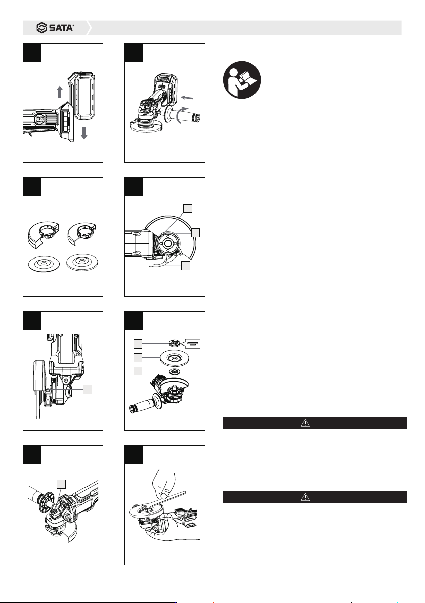
2) Installation and removal of battery pack (see
Figure A)
Press the lock buttons on both sides of battery pack
and pull it out. To insert the battery pack, simply push
it into the machine. Avoid the excessive force.
ASSEMBLY
WARNING
When installing or replacing the accessories, turn off
the switch and remove the battery pack. Otherwise
the serious injury may occur.
1. Installation of side handle (Figure B)
NOTE
Be sure to install the side handle securely before
operation.
Align the side handle with the threaded hole in the
gearbox and turn them clockwise until the side handle
is tightened;
Caution:
Please read the instruction
carefully before operating the machine.
B
C
fully-closed
cut off wheel grinding wheel
semi-closed
H
A
D
2
3
1
E
1
G
1
F
1
2
3
19
V_SC_5109NC_202104
2. Installation of shield and wheel (Figure C)
WARNING
The cut-off wheel is equipped with a fully-closed shield
and the grinding wheel blade is equipped with a semi-
closed shield. Moreover, the diameter of wheel shall
match that of shield.
Installation or removal of shield (see Figure D)
WARNING
When the tool is used, the shield shall be mounted on
the tool and the closed side of shield shall always face
the operator!
Installation of shield:
Step 1: open the shield lock (1);
Step 2: Align the bump (2) on the shield with the notch
on the gearbox;
Step 3: Press down the shield until the shield is
inserted into the gearbox, and the bump (2) is engaged
in the groove on the gearbox (3);
Step 4: Rotate the shield between the output shaft and
the operator. Select an appropriate angle, and then
lock the buckle (1).
Adjustment of shield: (Figure E)
When the shield is delivered, it has been pre-adjusted
to a position where it can be tightened. If the shield
becomes loose after a period of use, tighten the screw
(1) in the figure with the shield tightened. Removal of
shield:
In reverse order of installation: first loosen the buckle,
rotate the shield, and align the bump on the shield
with the notch on the gearbox and pull out the shield
vertically.
Installation and removal of wheel (see Figure F.G.H)
WARNING
When the tool is equipped with a wheel, be sure to use
the wheel shield. The wheel may be crushed during
use. The shield may help reduce the risk of personal
injury.
Installation of wheel:
Step 1: Turn off the switch and pull out the battery
pack
J
K
1
2
L
M N
inner pressure plate
external pressure plate
The thickness of disk is greater than 3MM
inner pressure plate
external pressure plate
The thickness of disk is less than 3MM
I

20
51091C/51090C
Step 2: Install the inner pressure plate without thread
on the spindle, with a side with step downwards, and
get it caught on the spindle
Step 3: Install the wheel on the inner pressure plate
Step 4: Drive the threaded outer pressure plate
clockwise into the spindle
Step 5: Press and hold the spindle lock button (1
in Figure G) to prevent the spindle from rotating.
Tighten the outer pressure plate clockwise with the
locking wrench(Figure H).
NOTE
(See Figure I.J)
When the thickness of wheel is greater than 3 mm,
the side of outer pressure plate with the center boss
is in contact with the wheel: when the thickness of
wheel is less than or equal to 3 mm, the side of the
outer pressure plate with the center groove is in
contact with the wheel.
Removal of wheel:
WARNING
The axis lock can only be used when the spindle
stops rotating.
After confirming the shutdown and unplugging the
battery pack, repeat the above steps in reverse
order.
OPERATION
WARNING
Do not operate the tool too hard. Excessive pressure
may cause damage to the wheel.
If the tool falls during the operation, be sure to
replace the wheel.
Never hit the workpiece with a backing pad or
grinding wheel.
The bounce and blockage of wheel shall be avoided
to prevent the wheel from rebounding, especially for
the processing of corner or sharp edge. Timber saw
blade and other saw blades are strictly prohibited.
The angle grinder with these saw blades will
frequently bounce up, and it is prone to runaway and
cause personal injury.
NOTE
The maximum cutting depth is 5mm. Adjust the
pressure on the tool so that the tool does not slow
down during operation.
After the operation, be sure to close the tool and
lower the tool only after the wheel has completely
stopped.
When the tool keeps operating until the battery is
exhausted, leave the tool for 15 min before replacing
the new battery pack.
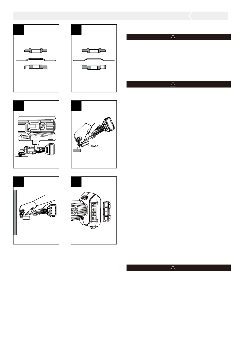
3. Switch (see Figure K)
Grasp the machine and the auxiliary handle, push the
lock button (1) forward, and then press the switch
trigger to start the machine.
4. Soft start
The machine has a soft start function. After the
start, the speed of machine gradually increases until
the maximum rotating speed. The comfort of start is
improved.
5. Electronic brake
During the operation, when the switch is released,
the electronic brake will start. Normally, the machine
will stop in 2S, and occasionally it may be greater
than 2S.
6. Grinding operation (Figure L)
NOTE
According to the material of workpiece, the wheel
of different material shall be selected, and the
recommended diameter is adopted. The maximum
rotating speed of wheel shall be more than 13000
rpm. The inner hole shall fit the pressure plate
tightly. Keep the working environment and workpiece
clean and tidy.
Place one hand on the outer casing, and the other on
the side handle, hold and start the tool, wait for the
tool to reach the maximum rotating speed, slowly
place the wheel on the workpiece, and then move