FF85-CT_Brochure_en-LR.pdf - 第6页
T o support our customers’ success, we created our Service Engine 4 . 0 including first-class technical problem- solving combined with high economic efficiency . This engine drives our service, our processes and our partne…
WHICH ITEMS AND MATERIALS ARE ESPECIALLY
SUITABLE FOR THE YXLON FF85 CT?
- aluminum, steel and super alloy components
- additive manufacturing samples
- fiber-reinforced composites
- plastic injection molded parts
- historical art and archeological objects
- geological samples
- biological samples
- mechatronic modules
You can easily combine the 2D Highly-Dynamic
Radioscopy (HDR) and 3D CT inspection tasks into one
sequence and graphically create your individual imaging
chain via drag and drop icons.
Use Yxlon’s helical CT scanning HeliExtend and
HeliExtend Dual for tall parts, create an accurate image
without the need of stitching and reduce artifacts for an
accurate, brilliant image.
You can further expand the bandwidth of inspection parts
by the use of ScanExtend, the Yxlon feature for horizontal
and/or vertical field-of-view extension.
The virtual rotation axis FlexCenter gives you the freedom
to inspect any region of interest in detail without having
to reposition the part physically. You even don’t need to
adhere to any sample positioning techniques, because
FlexCenter recognizes your part and defines the rotation
axis itself.
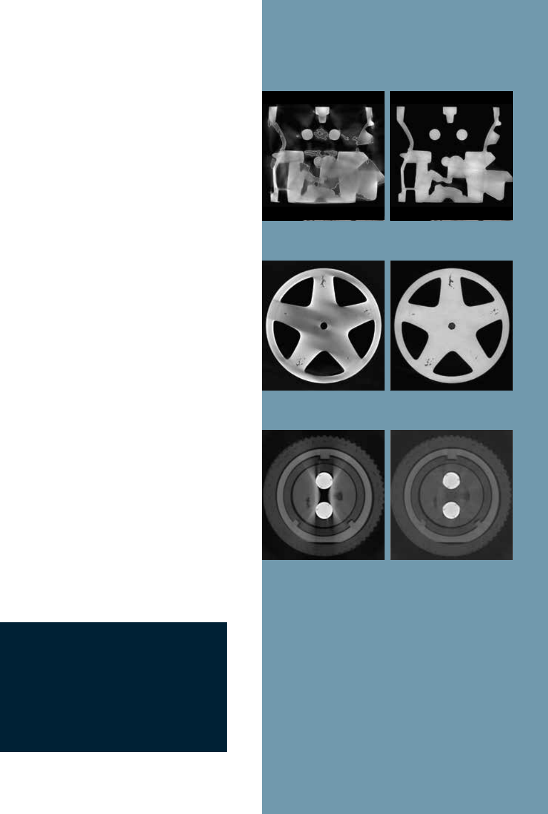
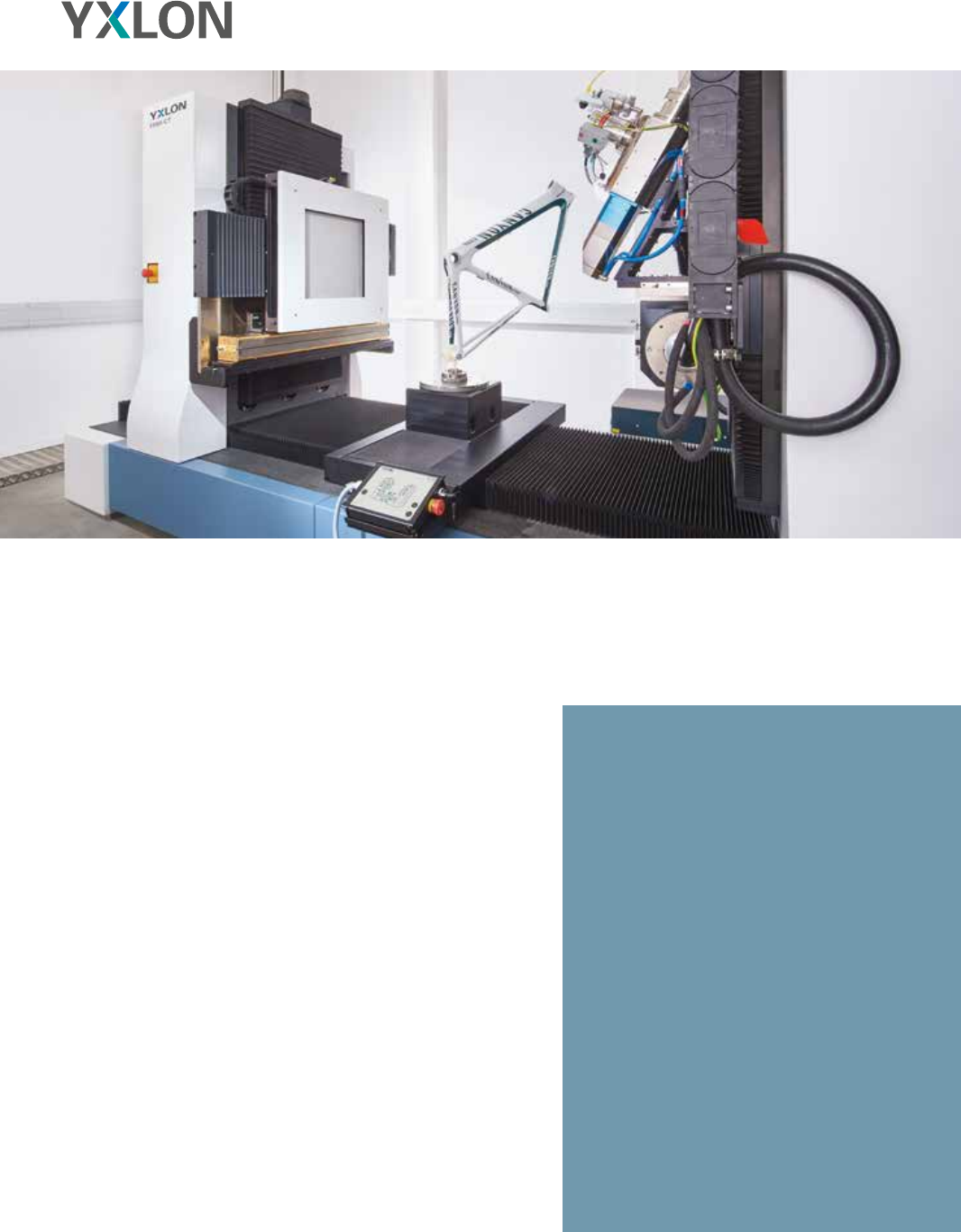
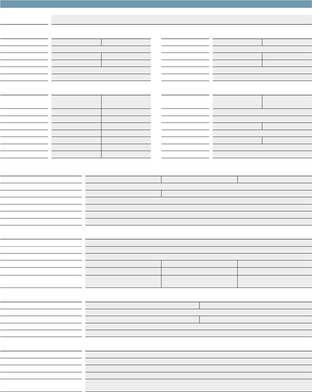
Additionally, you can apply software improvement tools:
ScatterFix: The innovative ScatterFix functionality
developed by YXLON reduces parasitic scattered radiation
and thereby improves the quality of the CT data. This
effect is an essential advantage, e.g. for an optimized
surface determination, when inspecting large, massive
and strongly scattering components.
Beam Hardening Reduction (BHC) can be used model
based for single-material objects or in multi-material
mode, where materials such as Carbon, Tungsten,
Aluminum and Steel can be selected.
Metal Artifact Reduction (MAR) reduces heavily
disturbing metal-induced artifacts in multi-material parts.
Get the most
out of your CT scans
5
Without Scatterfix With Scatterfix
Without BHC With BHC
Without MAR With MAR
To support our customers’ success, we created our
Service Engine 4.0 including first-class technical problem-
solving combined with high economic efficiency. This
engine drives our service, our processes and our partners
to detect and correct failures quickly and reliably by
remote access and during on-site visits. Our service
centers and our service partners worldwide are at your
disposal and can be contacted by phone, e-mail or via
our website.
YOU BENEFIT FROM
-
guaranteed operational safety
-
maximized system availability
-
minimized repair times
-
full cost control of life-cycle costs
-
extended product lifetime
-
maintaining the measuring capability of metrology
systems [FF20/35 CT Metrology]
Our module-based approach such as performance and
feature upgrades enable you to adapt to future require-
ments and safeguard your initial investment by extending
the product lifetime. With our Service Engine 4.0, fast
support for you is provided by the way we network all
service activities with our organization. We not only see
your immediate need but are predictive of your future
needs.
YXLON LIFECYCLE SERVICES
Academy – full performance from day one through
tailored training solutions
SmartExchange – direct replacement of defective
or worn-out components to minimize unscheduled
system downtime
SpareParts – 100% compatibility and safety
through Yxlon qualified spare parts
WarrantyPass – full cost control through our
customizable warranty extension program
ServicePass – predictive maintenance and
servicing, tailored to your requirements
SmartPass – maximum system uptime for
customers with particularly high demands
LifeCyclePass – all-inclusive concept for full
cost control over the entire product lifetime
Support – fully digitalized 1st-line support
organized in a worldwide expert network,
available remote or on-site
Upgrades – performance increase and new
features for your Yxlon system portfolio
YXLON Service Engine 4.0
6
YXLON FF85 CT
Inspection modes Cone-beam, helical, and fan-beam CT
X-ray components
X-Ray tube 1 Microfocus tube 225 kV Microfocus tube 300 kV X-Ray tube 2 Minifocus tube 450 kV Minifocus tube 600 kV
X-ray tube type Open, unipolar, micro-focus X-Ray tube type Sealed, bipolar, metal-ceramic, mini-focus
Maximum energy 225 kV 300 kV Maximum energy 450 kV 600 kV
Maximum power 320 W 350 W Focal spots 0.4 mm / 1.0 mm 0.7 mm / 2.0 mm
Target type Reflection target Maximum power 700 W / 1500 W
Detail visibility
≥
4 µm
1)
Target type Reflection target
Detectors
Detector 1
Flat Panel Detector
4343HE
Flat Panel Detector
4343N
Detector 2
Line Detector Array
CTScan 3-620
Line Detector Array
CTScan 3-780
Scintillator Gadox Gadox, CsI Scintillator CdWO
4
Maximum energy 16,000 kV 450 kV Maximum energy 600 kV
Active area 427 mm x 427 mm 432 mm x 432 mm Active area 620 mm 780 mm
Pixel pitch 139 µm 150 µm Pixel pitch 254 µm
Pixel matrix 3,072 x 3,072 2,880 x 2,880 Pixel matrix 2,432 3,072
Maximum frame rate 25 fps (3x3 binning) 60 fps (4x4 binning) Maximum frame rate 100 fps
Dynamic range 16 bit 16 bit Dynamic range 16 bit
Check out these facts
7
Manipulator Data
Configurations Microfocus – Flat panel detector Minifocus – Flat panel detector Minifocus – Line detector array
Max. FDD (Focus-Detector-Distance)
2)
2,000 mm or larger on request
Maximum magnification
2)
300 10
Maximum part size (Ø x h)
2)
1,000 mm (collision protected) x 2,000 mm or larger on request
Maximum part weight 400 kg
Manipulator dimensions
2)
3,600 mm length x 1,450 mm width x 2,550 mm height (or more for larger manipulators)
Manipulator weight
2)
9,000 kg (or more for larger manipulators)
CT parameter
Circular scan trajectories Continuous rotation “QuickScan“, start/stop scan “QualityScan”
Helical scan trajectories Standard helical CT “HeliExtend”, dual helical CT “HeliExtend Dual”
3)
Further trajectories Horizontal and / or vertical scan field extension, virtual rotation axis “FlexCenter”
3)
Configurations Microfocus – Flat panel detector Minifocus – Flat panel detector Minifocus – Line detector array
4)
CT field of view (circular, Ø x h)
5)
355 mm x 305 mm 365 mm x 325 mm 605 mm x 990 mm
2)
CT field of view (vertical & horizontal
scan field extension, Ø x h)
5)
680 mm x 1,300 mm
2)
710 mm x 1,085 mm
2)
980 mm x 990 mm
2)
Enclosure data
Maximum shielded energy 450 kV 600 kV
Enclosure dimensions (l x w x h)
2), 5)
5,150 mm x 2,650 mm x 2,880 mm
Enclosure weight
2), 5)
31,000 kg 52,000 kg
Loading door size (w x h)
2), 5)
1,000 mm x 2,200 mm
Internal crane Optional, maximum load 250 kg
Operator desk
Width ~ 1,800 mm
Height ~ 700 mm – ~ 1,200 mm, motorized
Depth ~ 800 mm
Weight ~ 175 kg
Monitor 2 pcs, capactive touchscreen, 1,920 x 1,080 pixel, 21",
as well as separate reconstruction and evaluation station with 30" monitor
1) With JIMA resolution test pattern for 2D at minimal focal spot size 2) approximate values 3) all available in “QuickScan” and “QualityScan” mode
4) Line Detector Array CTScan 3-780 5) larger values for larger manipulators