What is New in IPC-7351C.pdf - 第39页
PC B L ibr ar i es Pr e s ents : Wh at is N ew i n IPC- 7351C S old e r Joi nt Go al s f or Chip Co mp onent s Ch ip C apacitor Ch ip Fus e Ch ip T herm is t or Ch ip Non - p olar iz ed Diode Ch ip Inductor Ch ip V ar is…
PCB Libraries Presents:
What is New in IPC-7351C
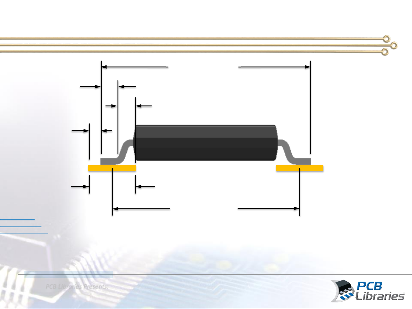
New Pad Center Calculation
Nominal “E”
Nominal “L”
Toe
Pad Length = Nom “L” + Heel + Toe
Heel
Pad Centers
Pad Length
Pad Centers = Nom “E” + 2 Toes – Pad Length
C
L
PCB Libraries Presents:
What is New in IPC-7351C
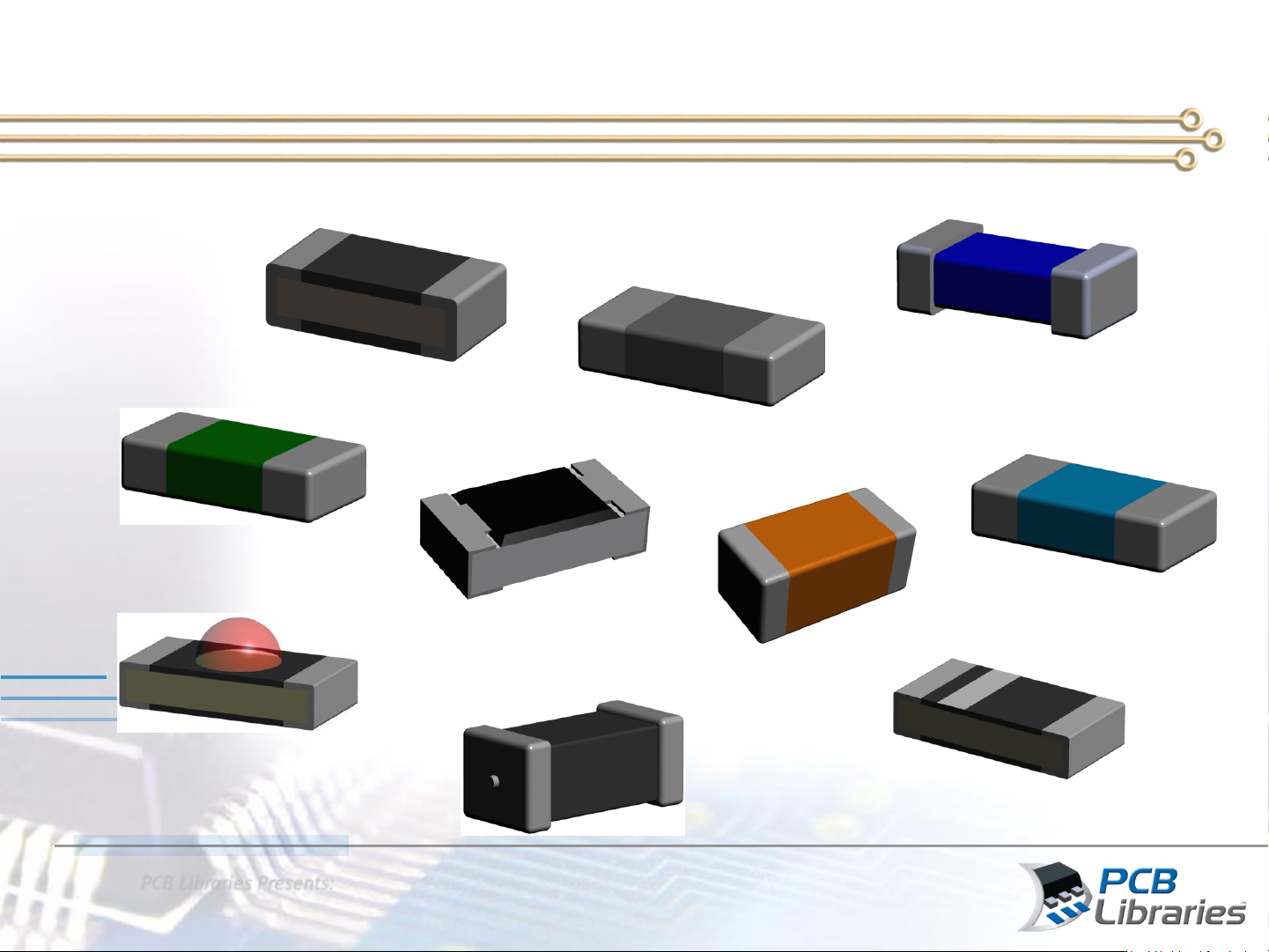
Solder Joint Goals for Chip Components
Chip Capacitor
Chip Fuse
Chip Thermistor
Chip Non-polarized Diode
Chip Inductor
Chip Varistor
Chip Resistor
Polarized Chip Capacitor
Chip Diode
Chip LED
PCB Libraries Presents:
What is New in IPC-7351C
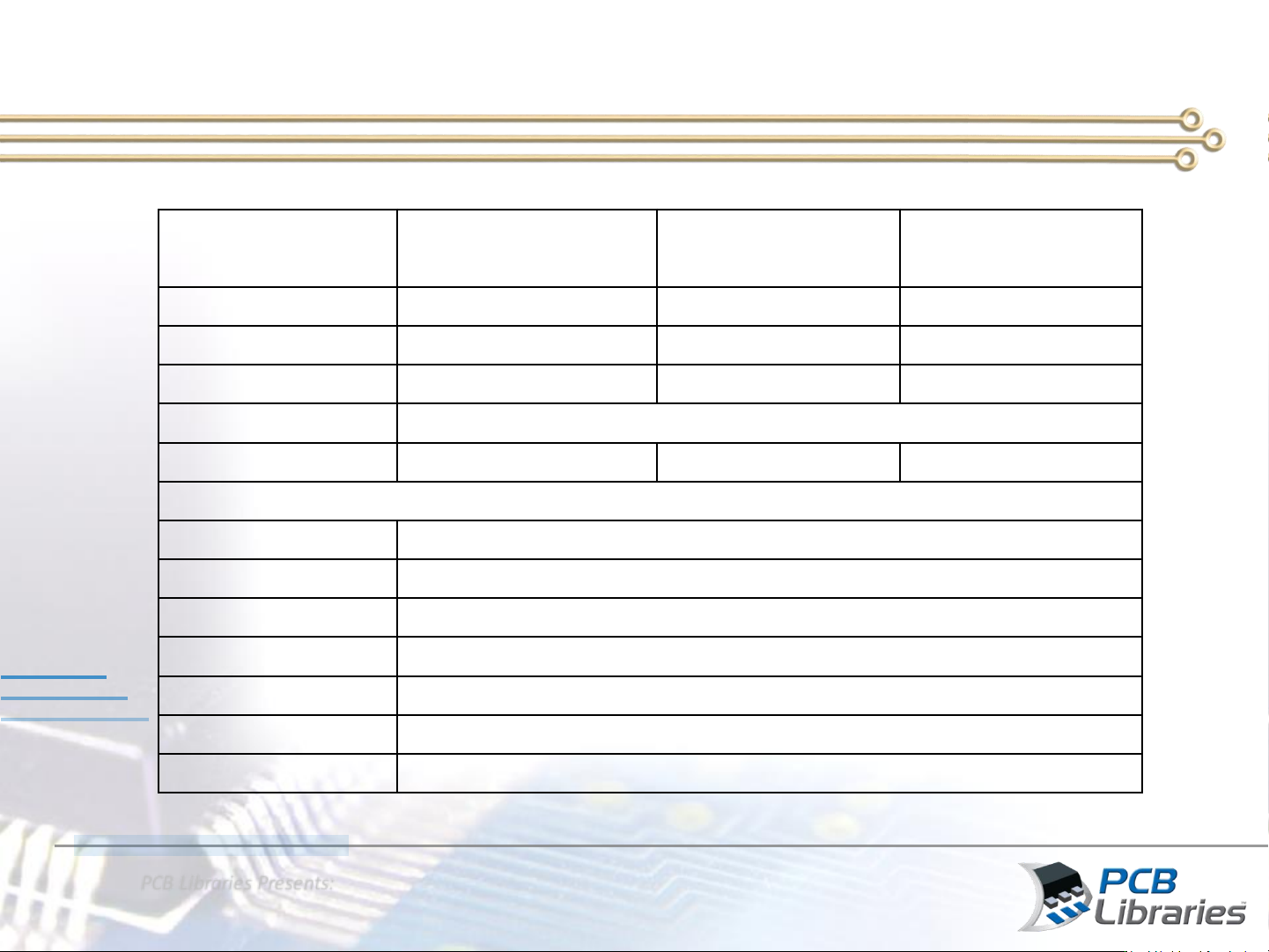
Lead Part
Maximum (Most)
Density Level A
Median (Nominal)
Density Level B
Minimum (Least)
Density Level C
Toe
(J
T
) 0.55 0.35 0.15
Heel
(J
H
) 0.00 0.00 0.00
Side
(J
S
) 0.05 0.00 -0.05
Round
-off factor
Round
off to nearest two place decimal, i.e., 1.00, 1.01, 1.02
Courtyard
excess 0.50 0.25 0.12
Rectangular Chip Components Smaller than 1608 (0603) (unit: mm)
Toe
(J
T
) 0402 0.15
Toe
(J
T
) 0201 0.12
Toe
(J
T
) 01005 0.10
Heel
(J
H
) 0.00
Side
(J
S
) 0.00
Round
-off factor
Round
off to nearest two place decimal, i.e., 1.00, 1.01, 1.02
Courtyard
excess 0.15
Solder Joint Goals for Chip Components < 0603