HS50 circuit diagram.pdf - 第136页
4 Printed Circui t Boards 136 I 0033145 1-020 201ND 3 826 board, C50 hea d boar d (Sh. 1 of 2) must be ju mpered. C&P-head : li ght bar rier, Z-axi s up LZOS V9 V14 V13 LSVA LSVZ V11 V12 V10 LSZD LSOI LZUS C&P- h…
4 Printed Circuit Boards 135
I
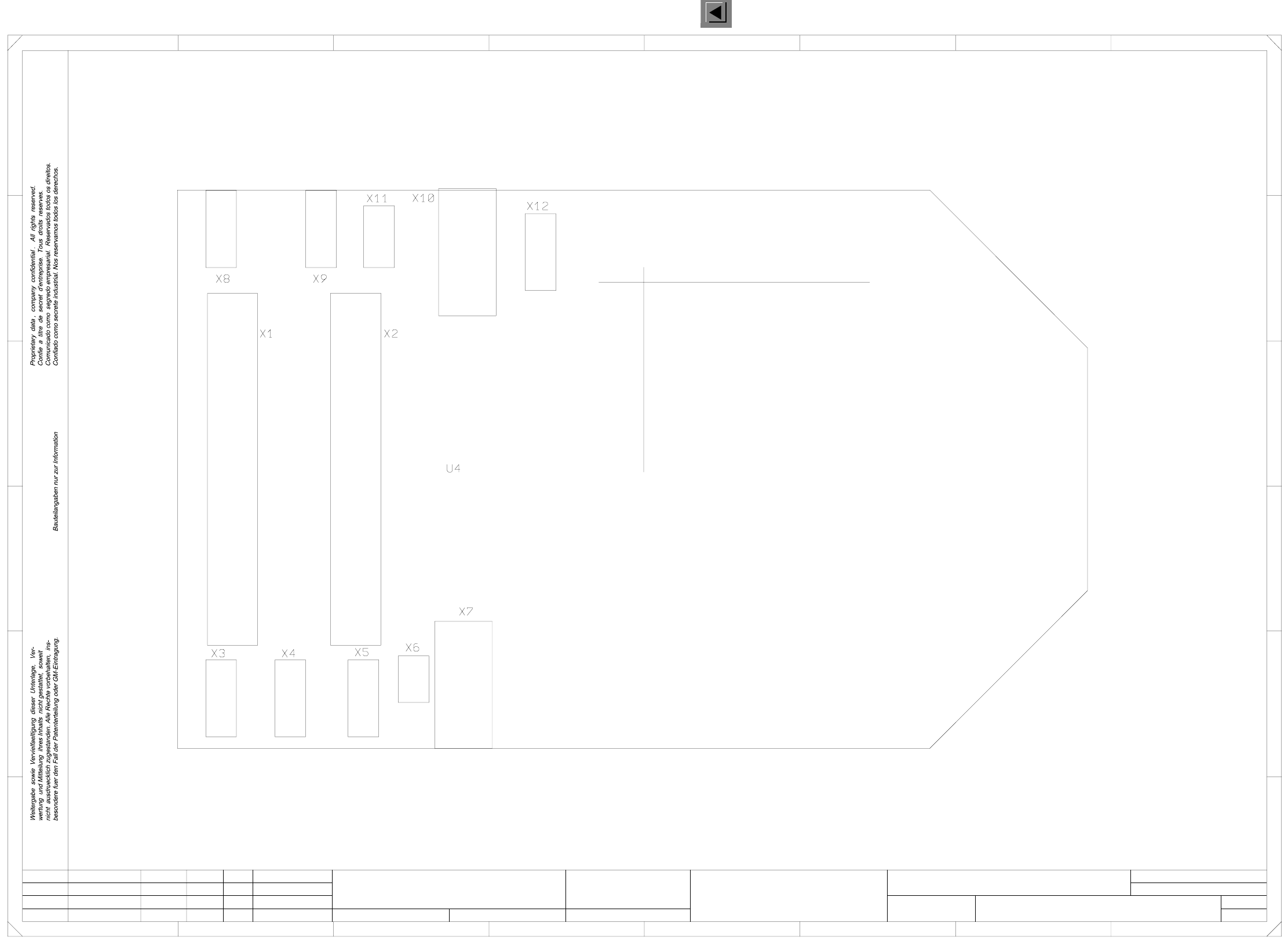
00330648-050101ND4 Intermediate distributor SP6-12, digital, component layout on top (Sh. 2 of 2)
=
Sheet
SIEMENS AG
Sh.
+
1 4
B
8
6
F
5
645
D
E E
23 78
C
B
A
32
D
C
F
A
71
01.
01.
05.
PL EA MUENCHEN
00330648-050101ND4
#
2
2
Product status
Doc. status
Function status
Intermed. distributor, SP6-12, digital SP6-12 Head
12.10.00 PIB
Bestueckungsplan / Comp. mount. diagr.
Status Modified Date Name
Date
Author
Check.
Stand. Orig. Repl. f. Replaced by
To X14, head board 00331451
Z-axis tachometer/motor
To X13, head board 00331451
AssemblyConnector
X3
X2
X1
X4 Z-axis measuring system
X5 DR-axis motor
X6 Forced air valve
X7 DP-axis measuring system
X8 Not used
X9 Not used
X10
X11
X12
Light barrier, Z-axis bottom
Light barrier, Z-axis top
DR-axis measuring system
4 Printed Circuit Boards 136
I
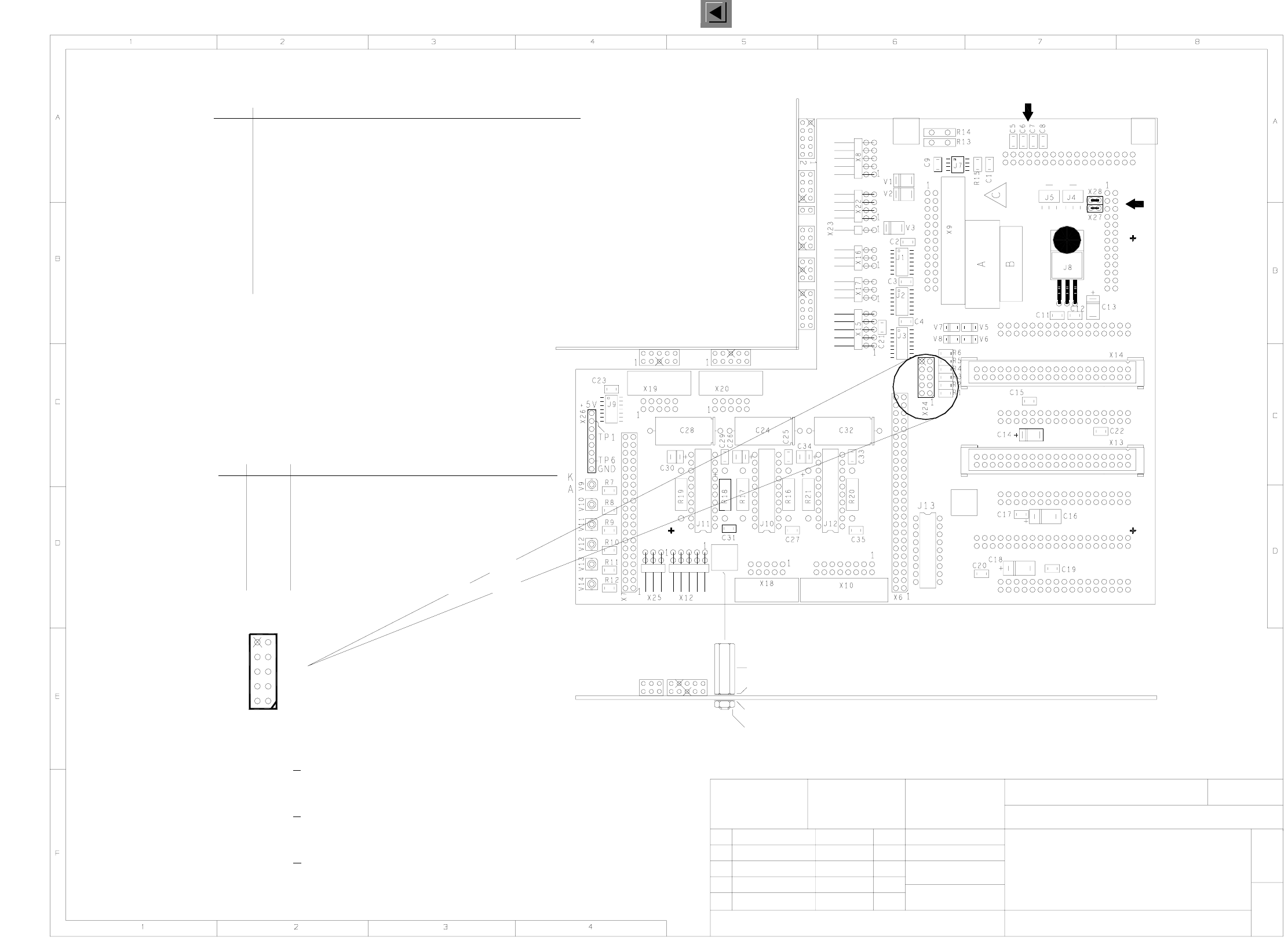
00331451-020201ND3 826 board, C50 head board (Sh. 1 of 2)
must be jumpered.
C&P-head: light barrier, Z-axis upLZOSV9
V14
V13
LSVA
LSVZ
V11
V12
V10
LSZD
LSOI
LZUS
C&P-head: light barrier swiveling in of turning station
C&P-head: light barrier vacuum/switching forced air in reject station
C&P-head: vacuum/switching forced air in placement circuit
P&P-head: light barrier up (not relevant)
C&P-head: light barrier, Z-axis down
LED Signal
Assembly
X15
X23
X25
X24
X18
X17
X16
X22
X20
X19
X6
X10
X14
X13
X12
X8
X9
X7
Plug
10
10
X24
9
3 Track A
Removed
Track N
Track N
9
8
+ 5 V
Track B
Track B
GND
5
7
6
4
Track A
Analog GND1
2
6
2
4
8
5
1
3
7
Test connector for X-axis track signals
To X1, adapter board 00330648
To X2, adapter board 00330648
To X1 on vacuum board 00347857
To X3 on component illumination 00321469
To X7, processor board 00331452
To X6, processor board 00331452
Measurement points for step motors (DP-axis, pickup/placement circuit, reject circuit)
la
Oblique lighting
Illumination for PCB camera 00315224
Valve adjustment drive for reject circuit 00349432
Valve adjustment drive for pickup station 00321217
Valve adjustment drive for DP-station 00350382
End pos. proximity switch 2 for X-axis 00335169
End pos. proximity switch 1 for X-axis 00335170
Incremental shaft encoder, X-axis, 00343441
Motor/tachometer, DP-axis 00321218
PCB camera 00315224
01
02
04
KL
KL
KL
26.03.97
Klose
26.03.97
09.05.00
22.09.97
SIEMENS AG
ATD TD MCH 2
2
1
4-layer printed circuit board
Mounting diagram, component side
C50 head board
826 board
G32918-J0008-B001-*-0017
main board
C = ESD label
B = Inspection label
A = Identification label
00331451-020201ND3
Spring washer
Nut M3
Washer
Distance bolt, 15 mm
Please note:
C5 - C8 not fitted
X27 and X28
Please note:
11
Stat. Modified Date Name
Date
Name
Sheet
Sh.
Scale 1:1
4 Printed Circuit Boards 137
I
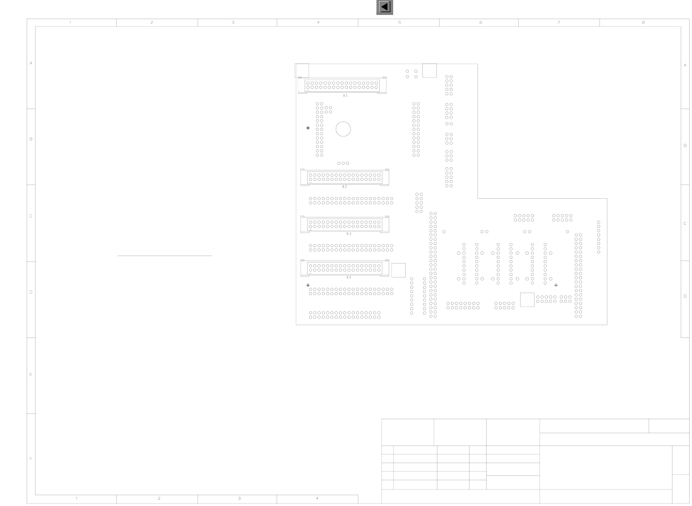
00331451-020201ND3 826 board, C50 head board (Sh. 2 of 2)
02
01 26.03.97
20.07.97
KL
KL
ATD TD MCH 2
SIEMENS AG
26.03.97
Klose
00331451-020201ND3
Main board
C50 head board
826 board
G32918-J0008-B001-*-0017
Mounting diagram, solder side
4-layer printed circuit board
2
2
Stat. Modified Date Name
Date
Name
Scale 1:1
Sheet
Sh.
X1
X3
X4
X2
AssemblyPlug
To X1 of gantry distributor 00335413
To X4 of gantry distributor 00335413
To X3 of gantry distributor 00335413
To X2 of gantry distributor 00335413
Please note: X5 will not be fitted
04 09.05.00 KL