HS50 circuit diagram.pdf - 第17页
1 Detailed Circuit Diagr ams 17 I NOTHAL T2 EMERG .-STOP loop, EMERG .-STOP butt ons, protective s witches (Sh. 2 of 2) Func tio n status Prod uct s tatus Doc. status SMD Plac ement Syst em SIPLACE H S50 NOTHALT-020101LD…
1 Detailed Circuit Diagrams 16
I
1
Detailed
Circuit
Diagrams
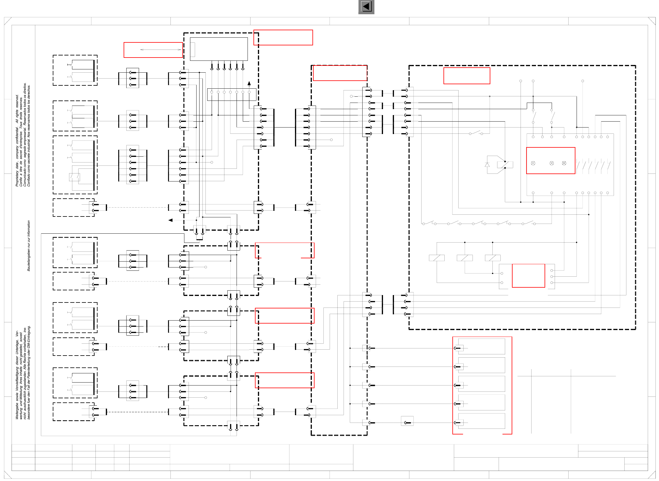
NOTHALT1 Emergency-stop loop, START buttons, STOP buttons, keyswitch (Sh. 1 of 2)
Function status
Product status
Doc. status
SMD Placement System SIPLACE HS50
servo
=
SIEMENS AG
+
W2
W2
W2
W2
Option
X1bf
Option
X1cf
Option,
external emerg.-
stop loop
Option
X1df
Option
ILS
bk
X96
00337809
00335266
X83
00335307
00335271
X84
00335306
00335275
bl
bk+wh
X85
00335307
bk
rd
bl
00336154
Power supply
W2
wh
rd
bk
rd
wh
rd
125kbps
X18dm
CAN bus
1
2
F
2P 34V
P 24V
NC_TapeCutter
Emerg. stop
S_StartButton
Ctrl_On
S_Ready
Control on
PCC
Channel2Channel1Power
00336145
Inrush current
infeed
limiter,
X12
X9do X2ah
infeed
Tape cutter (ah)00335235
X10do X2bh
infeed
Tape cutter (bh)00335236
X11do X2ch
72
7168
61
bk
Null
SZ23
K232
4
K14
SZ2
43
9
P34V
+24V
5
17c
SZ23
K234
21
73
66L- X4 X6
5343332313 65
1
2
2
1
1
2
1
2
1
22
00335248
X6cf
X6bf
X6af
Distributor, sector 2 (bf)
Distributor, sector 1 (af)
wh
X1af
Distributor, sector 3 (cf)
X3cf
X7cf
00335264
X12do X2dh
infeed
Tape cutter (dh)00335238
X13do X90
main valve
Tape cutter,
00335239
Main distributor (do)
00335245
X27do
00335246
X28do
00335247
X29do
3
X3bf
X7bf
00335260
X4af
00335262
bl
bk+wh
X82
00335306
F
X3af
X7af
8
A
2
D
3
C
B
A
5
B
rd
+24V
4
5wh
bk
A1A2
P34V
wh
bk
wh
4
1
7
bk
1bk+wh
bk4
5
wh
bk
2
+24V
4
5
5
1
rd
bk
1
4
Tape cutter (ch)00335237
4
4
3
3
00335244
X26do
X25do
00335223
X13
00335221
1
rd
bk+wh
X87
00335285
gn
rd
X4cf
X10df
X4df
X11df
41
E
5
4
X31do
X6df X3df
Distributor, sector 4 (df)
X24do
00335268
X7df
X12df
00329698
CAN I/O module 1
00335281
1
C
D
E
678
76
Side of power supply
X86
gn (W1)
rd (W1)
bk+wh+or (W1)
bk+wh (W2)
rd+gn (W2)
bl (W1)
wh+bk (W2)
00335283
gn (W1)
wh (W1)
rd (W1)
bl (W1)
bn (W1)
X4bf
00335284
gn
2.
1.
1.
01.07.01
01.07.01
01.07.01
01.07.2001
Hi
Emergency-stop loop
NOTHALT-020101LD3
1
Key
switch
W1
W2
W3
00335259
00336152
00336181
00336182
00336153
3
P24V
SZ4
4
3
2
Hi
Hi
Hi
6
bk
rd+gn
3
5
2
bk+wh
bl
5
6
wh
rd
bn
8
14 24
or+ye
5
6
9
4
5
bk
wh 5
rd
gn
4
or+ye
wh2
6
5
3
4
bl
bn
8
2
3
6
3
2
4
3
X5X3X1L+
4
34 44 54
1
vi+gy
2
8
gn
5
4
9
SZ3
21
SZ4
65
SZ4
wh
SZ2
K24
21
K34
bk 1
1
1
1bk
bk 1
1
1
1bk
SZ3
A1A2
SZ2
A1A2
1
SZ23
A1A2
rd
bk+wh
SZ4
2
1
2
1
gn
3
3
6
5
1
7
3
4
5
3
wh
2
1
bk
rd
bk
gn
rd
3
bk+wh
rd+gn
5
4
6
1
4
5
Start
3434
Stop
34 3434
3
bl
bk+wh
vi+gy
2
ye
7
1
rd
gn
rd
bk+wh
1
2
1
bk+wh
55
1
bl
bl
5
1
4
wh
wh
SD EA1 E2
5
bk+wh
55
bl
5
5
1
bl
5
rd
gn
P24V
+24V
wh
8
9
bk
7
bk+wh
343434
bl
1
2
bl (W1)
5
3
1
rd (W1)
wh+bk+bn (W1)
6
4
5
bl (W1)
rd+gn (W2)
wh+bk (W2)
rd (W1)
gn (W1)gn (W1)
rd+gn (W2)
bk+wh (W2)
bk+wh+bn (W1)
2
5
supply
Sheet
Sh.
NOTHALT1.DWGCAD file:
Orig. Repl. f. Replaced by
Date
Author
Check.
Stand.NameDateModifiedStatus
Di1
bk
S2
S2
S1
S2
S1
S4
S3
rd+gn (W2)
bk (W1)
S2
W1
W2
W1
Warning !
If cables are used corr. to the DIN 47100 color code, please use the table below!
The wire colors in the drawing correspond to the Belden color code.
4
12
8
11
10
9
6
7
5
2
3
1
Wire
Greengn
Tanlibn
Pink
Violet
Orange
Brown
Yellowye
pk
gy
vi
Gray
bl
or
bn
Blue
White
Black
Belden color code
wh
rd
bk
Red
Yellowye
rd+bl
rd
gypk
vi
bk
pk
bl
gy
red+blue
Red
Gray+Pink
Violet
Black
Blue
Pink
Gray
DIN 47100 color code
bn
gn
wh
Green
Brown
White
START buttons STOP buttons
Keyswitch
SSK54
SSK53
SSK43
SSK44
SSK53
SSK54
SSK43
SSK44
N. u.
N. u.
N. u.
N. u.
S1
S1
StartStartStart
PCB output, righth. side
Start Stop Start
Pneumatic panel PCB input, lefth. side
bk+wh
2P34V
P34V
16c
18c
23c
20a
21c
22c
X400
Sector 4
To sheet 2
X400:20b
X2
X1
X11
X6
X7
X8
dm:1
dm:1
dm:1
dm:1
dm:2
55
bl
77
ye
777
ye
ye
6or
6or
6or
6 orgn
rd
gn
1
bk+wh
6
5
or
bl
gn
rd
1
5
bk+wh
bl
6or
gn
bk
34
S2
Stop
external emerg.-
stop loop
Option,
PCB output, lefth. sidePCB input, righth. side
external emerg.-
stop loop
Option,
gn
Stop
S3
3443
Stop
S2
bk
gn
external emerg.-
stop loop
Option,
gn or6 or 6
S3
Stop
3 4
gn
wh
wh
7
bl
ye
bk+wh
bk+wh
bk+wh
X400:17b
X400:10a
dm:1
S_StartButton
Emerg. stop
Ctrl_On
S_Ready
Control on
2P 34V
S_StartButton
16c
17c
S_StopButton
20a
18c
Emerg.Stop
S_KeySwitch
21c
22c
23c
Ctrl_On
S_Ready
Control On
X400:
See page 97
See page 103
See page 87
See page 107
See page 105
See page 92
See page 87
See page 132
See page 45
See page 89
1 Detailed Circuit Diagrams 17
I
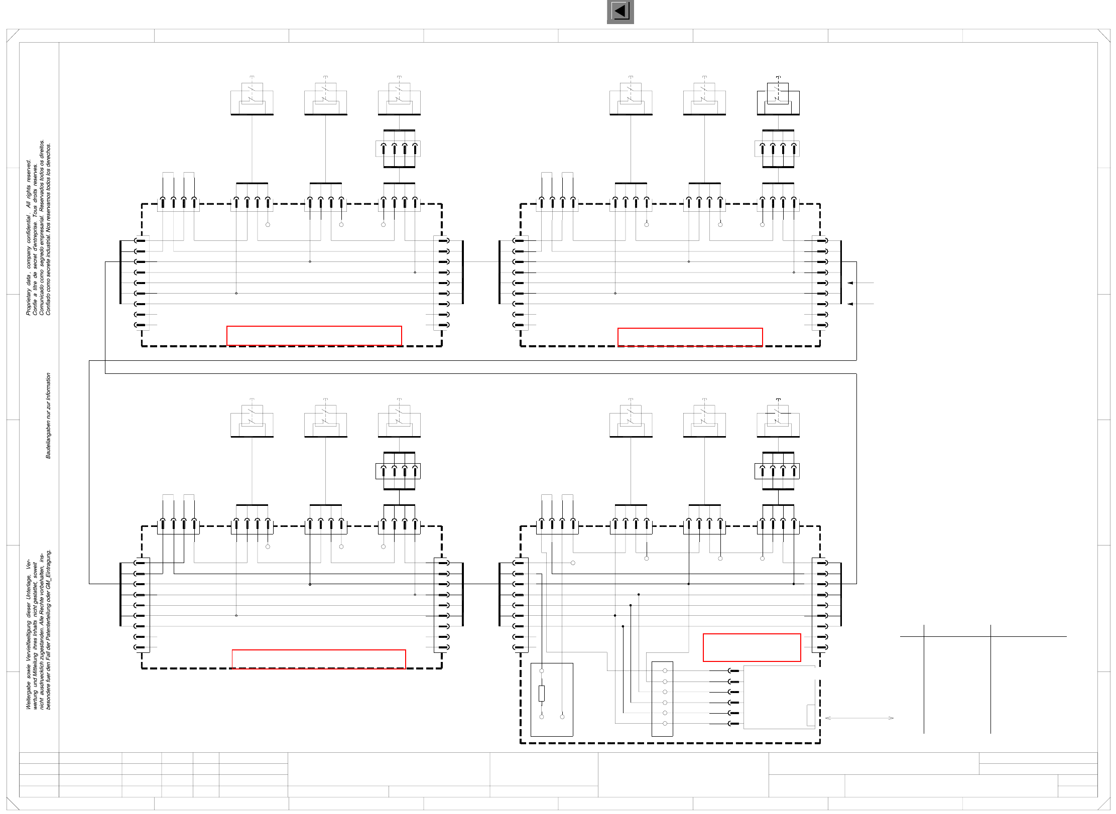
NOTHALT2 EMERG.-STOP loop, EMERG.-STOP buttons, protective switches (Sh. 2 of 2)
Function status
Product status
Doc. status
SMD Placement System SIPLACE HS50
NOTHALT-020101LD3
Replaced by
Sheet
Sh.
NOTHALT2.DWG
SD EA1 E2
CAD file:
Status Modified Date Name Stand.
Check.
Author
Date
Orig. Repl. f.
S826 b (S1) (S1) (S1)
1
3
2
4
7
8
9
8
9
7
5bl 5bl
yeye
N. u.
N. u.
N. u.
N. u.
See sheet 1
See sheet 1
bl 5 5bl
ye
N. u.
N. u.
7
8
9
7
8
N. u.
N. u.
ye
bl
55bl
8
9
7
N. u.
N. u.
ye
8
9
7
N. u.
N. u.
ye
5
bl
5bl
N. u.
N. u.
ye
9
8
7
8
9
7
N. u.
N. u.
ye
16a,c
17a,b,c
X8dm:1
X7dm:1
S_StartButton
S_StopButton
S_StopButton
S_StartButton
S826 b (S1) (S1) (S1)S826 b (S1) (S1) (S3)
S826 b (S1) (S1) (S3)
1
3
2
4
The wire colors in the drawing correspond to the Belden color code.
If cables are used corr. to the DIN 47100 color code, please use the table below!
Warning !
4
12
8
10
11
9
6
7
5
2
3
1
Wire
ye Yellowgn Green
libn Tan rd+bl
Yellow
Brown
Orange
Violet
ye
gy
pk
vi
Gray
Pink
bl
or
bn
Blue
rd
vi
gypk
bk
pk
bl
gy
Red+Blue
Red
Black
Violet
Gray+Pink
Gray
Pink
Blue
DIN 47100 color codeBelden color code
Black
Whitewh
rd
bk
Red
bn
gn
wh White
Brown
Green
Protective switches
Emergency-stop buttons
rd
or
bn
gn
bk+wh bk+wh
gn
bn
or
rd
bk+wh
gn
bn
or
rd
X300:7b
+24V
X300:7c X300:7a
+24V
X100:7a
+24V
X100:7b
+24V
X100:7c
+24V
X200:7c
+24V
X200:7b
+24V
X200:7a
+24V
+24V
X400:11c X400:9b
+24V
X400:9a
+24V
X400:9c
+24V
S_Comp. flap,
S_Comp. table,
S_Emerg. stop b.,
S_Cover,
X400
R1
X400
+24V
30a 30c
6-pole12-pole
12-pole 6-pole 12-pole
12-pole 6-pole
6-pole
6-pole
6-pole6-pole
6-pole
3
2
4
bk
wh
rd
gn
Cover, input
00335307-W1
13
21
14
22
ye
wh
bn
gn
13
21
00337737
0033773700337737
Emerg.-stop
(loop end)
wh
bn
gn
13
21
14
22
00335263
ye
wh
bn
gn
13
21
14
22
00335263
ye
wh
bn
gn
13
21
14
22
3
1
D
C
1
gn
3
1
4
2
bn
wh
ye
gn
3
1
4
2
bn
wh
ye
gn
3
1
4
2
bn
wh
ye
gn
Comp-ProtectiveFlap4
00337737
gn
wh
X82
00335262
00329698
CAN I/O module
bk+wh
rd
gn
bn
or
00335268
Status illustrated in this drawing:
covers closed,
emergency-stop buttons not pressed.
S_Cover
X17dm
A2 (dm)
X4dm:1
X9dm:1
X5dm:1
X3dm:1
125kbps
CAN bus
wh
rd
gn
X84
S_Emerg.StopB
S_Comp.Table
S_Comp. flap
rd
gn
rd
bk
Cover, output
D
3
C
B
A
5
B
32
F
41
E
5
4
F
Distributor, sector 4 (df)
rd
bkbn
rd
gn
bk+wh
4
1
3
bk+wh
8
A
2
gn
bk+wh
gn
rd
bn
Prot. cover 4
wh
rd
bk
X85
00335275
bn
rd
gn
bk+wh
gn
Prot. cover 1
wh
wh
X6df
X4dfX5dfX25df
00335266
X83
ye
00335306-W2
wh
Prot. cover 2
ye
gn
bk
bk
wh
bn
Emerg.-stop, output, righth. s.
bn
00335271
wh
gn
rd
bk
bk+wh
gn
rd
bn
gn
00335263
2
00335260
13
21
00335307-W1
Distributor, sector 2 (bf)
X3cf
X1cf X25cf X5cf X4cf
X6cf
Distributor, sector 3 (cf)
Comp-ProtectiveFlap3 Prot. cover 3
00337052
E
678
76
gn
bn
or
00335264
X3bf
gn
X1df
X3df
00335259
or
bn
gn
rd
bk+wh
or
bn
bk+wh
rd
X25afX1af
Distributor, sector 1 (af)
X6af
X4afX5af
X3af
22
14
1.
1.
2.
Hi
Hi
Hi
2
X6bf
X4bfX5bfX25bfX1bf
rd
gn
bn
or
bk+wh
rd 2
2
Emergency-stop loop
Hi
01.07.2001
01.07.01
01.07.01
01.07.01
bn
3K3
4
4
1
2
4
1
bk+wh
rd
15a,c
14a,c
gn
bn
6
20b
4
1
13a,c
24a,b,c
6
2
3
4
3
6
2
1
4
3
3
2
1
2
4
1
rd
bk+wh
1
3
gn
A5
2
4
A6
A3
1
3
A4
3
6
4
1
4
3
2
+24V
3
4
3
6
2
1
4
1
3
bn
bk+wh
rd
1
gn
2
6
4
A5
3
6
4
2
2
3
1
2
1
1
3
2
4
A6
A3
A5
gn
3
A4
1
4
2
6
3
1
3
2
2
4
4
1
3
A5
2
A4
A6
A3
4
1
3
bk+wh
rd
2
bn
2
4
A4
3
1
A3
A6
=
SIEMENS AG
+
2
4
3
1
4
00336152
0033618100336182
00336153
Comp-ProtectiveFlap2
00337052
ye
gn
bn
wh
14
22
00335263
ye
00337052
ye
gn
bn
wh
Comp-ProtectiveFlap1
00337052
ye
gn
bn
wh
gn
bn
wh
ye
gn
bn
wh
ye
gn
bn
wh
ye
1
3
4
2
bn
wh
ye
2
wh
rd
gn
bk
Emergency-stop, input, righth. s.
00335306-W2
1
See page 107
See page 105
See page 92
See page 97
1 Detailed Circuit Diagrams 18
I
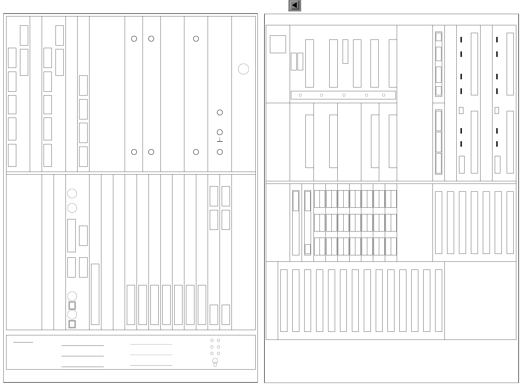
00343070-020101GD41 HS-50 control unit (viewed from the front)
00343070-020101GD42 HS-50 control unit (viewed from the back)
X2so X6so X7so
X3sm
Floppy
Hard disk o
X2sn X6sn X7sn
X3sk
X3sh
X3sg
X3sf
X3se
X3sd
X7sa
X6sa
X8sa
X9sa
X10
X5
X11 X12
LAN1 LAN2
M54
Axis board 1
Axis board 2
Axis board 3
Axis board 4
Axis board 5
Axis board 6
Axis board 7
COM 1 COM 2
Reserved for M54 GEM
Reserved for Floppy/Hard disk, GEM
Reserved for PCI
Spare
DIAGNOSIS
Reserved for PCI
Spare
+ 52V
+ 5V + 24V - 15V
+ 5V + 15V
- 12V
+ 12V
Battery +3.8V
X2sv X3sv X4svX1sv
Video multiplexer
ICOS 2
ICOS 1
X3su
X7su X9su X5su X8suX6su
X4su
X3st
X7st X9st X5st X8stX6st
X4st
Firmware Version : Axes :
Spare
X1
0
Y1
1
S1
2
X2
3
Y2
4
S2
5
X3
6
Y3
7
S3
8
X4
9
Y4
10
S4
11
Z1
12
D1
13
Z3
14
Z2
15
D2
16
D3
17
Z4
18
D4
19
20
BE
ON
IN
CE
0
ED
Board error
Initialized
Servo on
Count. error
Zero pulse
End
OFF Servo on
Servo off
Control unit, HS50 (viewed from the front)
00343070-020101GD41 05.11.99
X1sy
X2sy
X3sy
X4sy
X5sy
X6sy
X7sy
X8sy
X9sy
X10sy
X11sy
X12sy
X13sy
X14sy
X3sz
X4sz
X5sz
X6sz
X7sz
X1sz
X2sz
X4tr X2trX6tr
X3tr X1trX5tr
X4tq X2tqX6tq
X3tq X1tqX5tq
X4tp X2tpX6tp
X3tp X1tpX5tp
X4to X2toX6to
X3to X1toX5to
X4tn X2tnX6tn
X3tn X1tnX5tn
X4tm X2tmX6tm
X3tm X1tmX5tm
X4tk X2tkX6tk
X3tk X1tkX5tk
X25
X24
X22
X23
X20
X1th
X2th
X4th
X5th
X3th
X7th
X8th
X6th
X9th
1 2 3 4 5
X9tg
X10tg
X5tg X6tg X11tg
X8tg
X1tg X2tg X3tg X4tg
X9tf
X10tf
X5tf X6tf X11tf
X8tf
X1tf X2tf X3tf X4tf
1
X34 X33
1
1
X36
8
18
28
X35
1
2
3
26
Control unit, HS50 (viewed from the back )
00343070-020101GD42 05.11.99