plug-play-automatic-feed-soldering-jbc-0033471_ID-245332_EN.pdf - 第6页
EAR TH FUSE F1.25 A USE ONL Y WITH A 250 V FUSE EAR TH FUSE F1.25 A ALE250 ALE250 ALE250 ALE250 ALE250 ALE250 ALE250 ALE250 ALE250 6 3 1 2 4 5 3 1 2 6 ALE250 Automa tic-Feed Soldering Iron Gu ide Nozzle T ool Connect or …
EARTH FUSE F1.25 A
USE ONLY WITH A 250 V FUSE
EARTH FUSE F1.25 A
EARTH FUSE F1.25 A
USE ONLY WITH A 250 V FUSE
EARTH FUSE F1.25 A
EARTH FUSE F1.25 A
USE ONLY WITH A 250 V FUSE
EARTH FUSE F1.25 A
EARTH FUSE F1.25 A
USE ONLY WITH A 250 V FUSE
EARTH FUSE F1.25 A
ALE250
ALE250
ALE250
3
1
4
5
3
3
1
2
2
3
5
40 mm
50 mm
60 mm
80 mm
100 mm
130 mm
130 mm
para manuales - negro plano
200 mm
300 mm
Mark
Step 3 Cartridge Assembly
For a safe cartridge assembly/change, make sure that the tool is
unplugged and the cartridge has cooled down.
Loosen the cartridge set screw (1) and insert the cartidge up to its
mark (2). Important: It is essential to insert the cartridge completely
for a good connection.
Adjust the tip direction (3) and tighten the cartridge set screw (1).
Top View
of the Reel Locking
Flat Side
(Reel Locking and Axis)
Reel Locking
Screw
Flat Side
of the Axis
Flat Side of the
Reel Locking
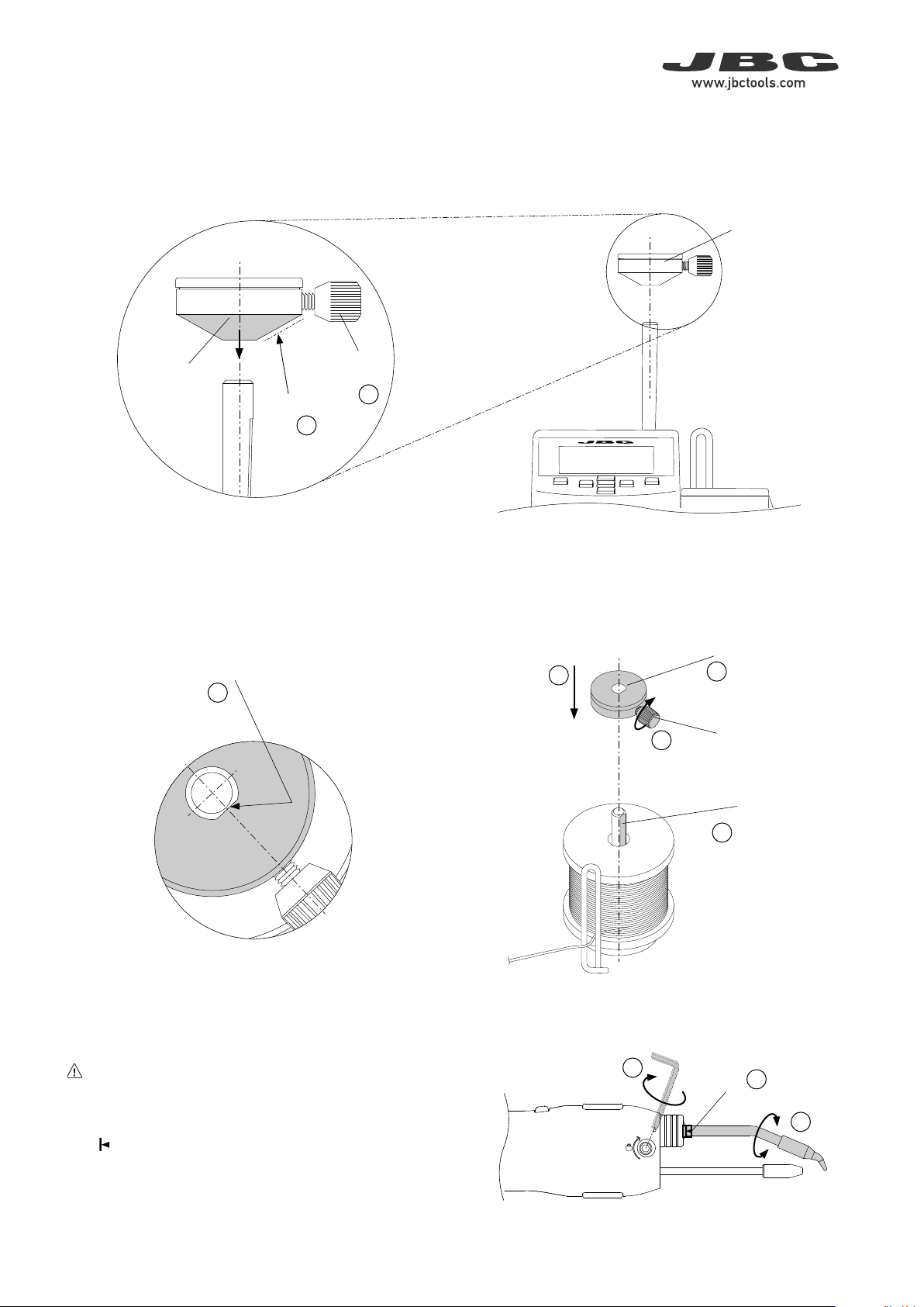
Step 2 Reel Locking Assembly
Reel Locking
Reel Locking
Conical
Side
To assemble the reel locking, its conical side must be pointing
downwards (1).
Make sure that the reel locking screw is slightly backed out and does
not collide with the axis (2).
Align the flat side of the axis with the inner flat side of the reel locking
(3) and assemble the reel locking to the axis (4).
Note: To prevent the solder reel from spinning freely or binding, gently
press the reel locking down, but only enough to allow the solder reel
to rotate freely, before tightening the reel locking screw (5).
Reel Locking
Screw
EARTH FUSE F1.25 A
USE ONLY WITH A 250 V FUSE
EARTH FUSE F1.25 A
ALE250
ALE250
ALE250
ALE250
ALE250
ALE250
ALE250
ALE250
ALE250
6
3
1
2
4
5
3
1
2
6
ALE250
Automatic-Feed Soldering Iron
Guide
Nozzle
Tool Connector
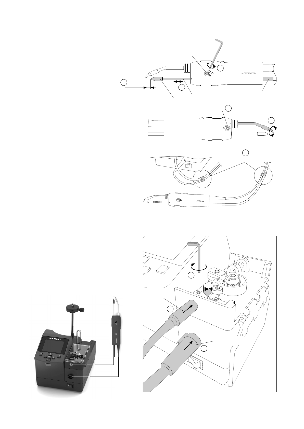
Connect the tool to the control unit following
these steps:
Loosen the set screw (1), insert and push
the guide nozzle until it stops (2) and tighten
the set screw (1).
Then plug in the tool connector (3).
Step 5 Tool Assembly
Loosen the guide tube set screw (oppo-
site direction to that indicated on the tool
casing) (1) and insert the guide set.
Adjust the guide tube length (2). Leave a gap
of 5 to 7mm (0.197 to 0.276in) between the
tip and the outlet nozzle (3).
If necessary adjust the cartridge tip direction
(4) to match the point where the wire will
come out. To do this, open the cartridge
set screw and tighten it when it is done (5).
Once the guide tube set position is adjusted
tighten the guide tube set screw (1).
For a better handling use the clips (6) to band
the guide tube and the tool cable together.
Step 4 Guide Set Assembly
Clips
Outlet
Nozzle
Guide Nozzle
5-7 mm
0.19-0.27 in
Guide Tube
Set Screw
Guide Set
Cartridge Set
Screw
1
2
Language
Feeder sengs
Staon sengs
Tool sengs
Counters
Reset
Tin reload process
Tin reload process
Mode
Connuous
5.0mm/s
1.00mm
On
On
Speed
Wire diameter
Feeder parameters lock
Wire clogging detecon
None
Backward
Back
Tin reload process
Forward
Backward
Place the n on the gears
and press:
Press ok to exit
Program
Connuous
Disconnuous
Mode
Back
0.5
mm/s
25%
75%
Power
Connuous
50%
19:29
Sel. Temp.
350
º
C
Ø 1.00 mm
Supplied: 0 mm
350
º
C
0.5
10.0
25%
75%
Power
Disconnuous
50%
19:29
Sel. Temp.
350
º
C
Ø 1.00 mm
350
º
C
mm/s
mm
25%
75%
Power
50%
19:29
Sel. Temp.
350
º
C
350
º
C
3
2
1
Program #1
Ø 1.00 mm
Feeder parameters lock
None
On
On
Edit program
Programs loaded
Set default programs
Backward
1.00mm
Wire diameter
Wire clogging detecon
Back
Mode
Program
Edit program
Program #1
Length
Speed
3
2
1
mm
1.0
5.0
5.0
5.0
2.0
2.0
mm/s
Edit program
Length
Speed
3
2
1
mm
None
None
None
None
2.0
2.5
mm/s
Program #4
Tin reload process
Staon sengs
Counters
Language
Reset
Tool sengs
Feeder sengs
English
Deutsch
Español
Italiano
Français
日本語
한국어
Português
Pусский
Program version
8886732
Maximum temp
400
º
C
Off
200
º
C
On
º
C
mm
Minimum temp
Sound
PIN
Temp units
Length units
Staon reset
Back
Temp adjust
0
º
C
Temp level set
Off
10min
0min
150
º
C
Sleep delay
Peripher.
Sleep temp
Hibernaon delay
Back
Plug hrs
28
Working hrs
Part
Tot
6
0
0
0
20
1
2
1
24
20
181
19
22786
118
Sleep hrs
Sleep cyc
Fed cyc
Fed mm
Hiber hrs
No tools hrs
Feeder parameters lock
20.0mm/s
None
1.00mm
12.0mm
On
On
Speed
Wire diameter
Length
Backward
Wire clogging detecon
Back
Mode
Disconnuous
Mode
Connuous
5.0mm/s
1.00mm
Off
None
Speed
Wire diameter
Feeder parameters lock
Backward
On
Wire clogging detecon
Back
325
º
C
24.0
mm/s
25%
75%
Power
Connuous
50%
Sel. temp. 325
º
C
Ø 1.00 mm
Supplied: 12 mm
1.00mm
Updang
Your staons is being updated
No
Do you want to update firmware?
Yes
Language
Feeder sengs
Staon sengs
Tool sengs
Counters
Reset
Tin reload process
Language
Feeder sengs
Staon sengs
Tool sengs
Counters
Reset
Tin reload process
Tin reload process
Mode
Connuous
5.0mm/s
1.00mm
On
On
Speed
Wire diameter
Feeder parameters lock
Wire clogging detecon
None
Backward
Back
Tin reload process
Forward
Backward
Place the n on the gears
and press:
Press ok to exit
Program
Connuous
Disconnuous
Mode
Back
0.5
mm/s
25%
75%
Power
Connuous
50%
19:29
Sel. Temp.
350
º
C
Ø 1.00 mm
Supplied: 0 mm
350
º
C
0.5
10.0
25%
75%
Power
Disconnuous
50%
19:29
Sel. Temp.
350
º
C
Ø 1.00 mm
350
º
C
mm/s
mm
25%
75%
Power
50%
19:29
Sel. Temp.
350
º
C
350
º
C
3
2
1
Program #1
Ø 1.00 mm
Feeder parameters lock
None
On
On
Edit program
Programs loaded
Set default programs
Backward
1.00mm
Wire diameter
Wire clogging detecon
Back
Mode
Program
Edit program
Program #1
Length
Speed
3
2
1
mm
1.0
5.0
5.0
5.0
2.0
2.0
mm/s
Edit program
Length
Speed
3
2
1
mm
None
None
None
None
2.0
2.5
mm/s
Program #4
Tin reload process
Staon sengs
Counters
Language
Reset
Tool sengs
Feeder sengs
English
Deutsch
Español
Italiano
Français
日本語
한국어
Português
Pусский
Program version
8886732
Maximum temp
400
º
C
Off
200
º
C
On
º
C
mm
Minimum temp
Sound
PIN
Temp units
Length units
Staon reset
Back
Temp adjust
0
º
C
Temp level set
Off
10min
0min
150
º
C
Sleep delay
Peripher.
Sleep temp
Hibernaon delay
Back
Plug hrs
28
Working hrs
Part
Tot
6
0
0
0
20
1
2
1
24
20
181
19
22786
118
Sleep hrs
Sleep cyc
Fed cyc
Fed mm
Hiber hrs
No tools hrs
Feeder parameters lock
20.0mm/s
None
1.00mm
12.0mm
On
On
Speed
Wire diameter
Length
Backward
Wire clogging detecon
Back
Mode
Disconnuous
Mode
Connuous
5.0mm/s
1.00mm
Off
None
Speed
Wire diameter
Feeder parameters lock
Backward
On
Wire clogging detecon
Back
325
º
C
24.0
mm/s
25%
75%
Power
Connuous
50%
Sel. temp. 325
º
C
Ø 1.00 mm
Supplied: 12 mm
1.00mm
Updang
Your staons is being updated
No
Do you want to update firmware?
Yes
Language
Feeder sengs
Staon sengs
Tool sengs
Counters
Reset
Tin reload process
7
40 mm
50 mm
60 mm
80 mm
100 mm
130 mm
130 mm
para manuales - negro plano
200 mm
300 mm
Step 7 Station Set Up
P405
Pedal
ALES
Stand for ALE250 Automatic-Feed
Soldering Iron
ALE
Automatic-Feed Control Unit
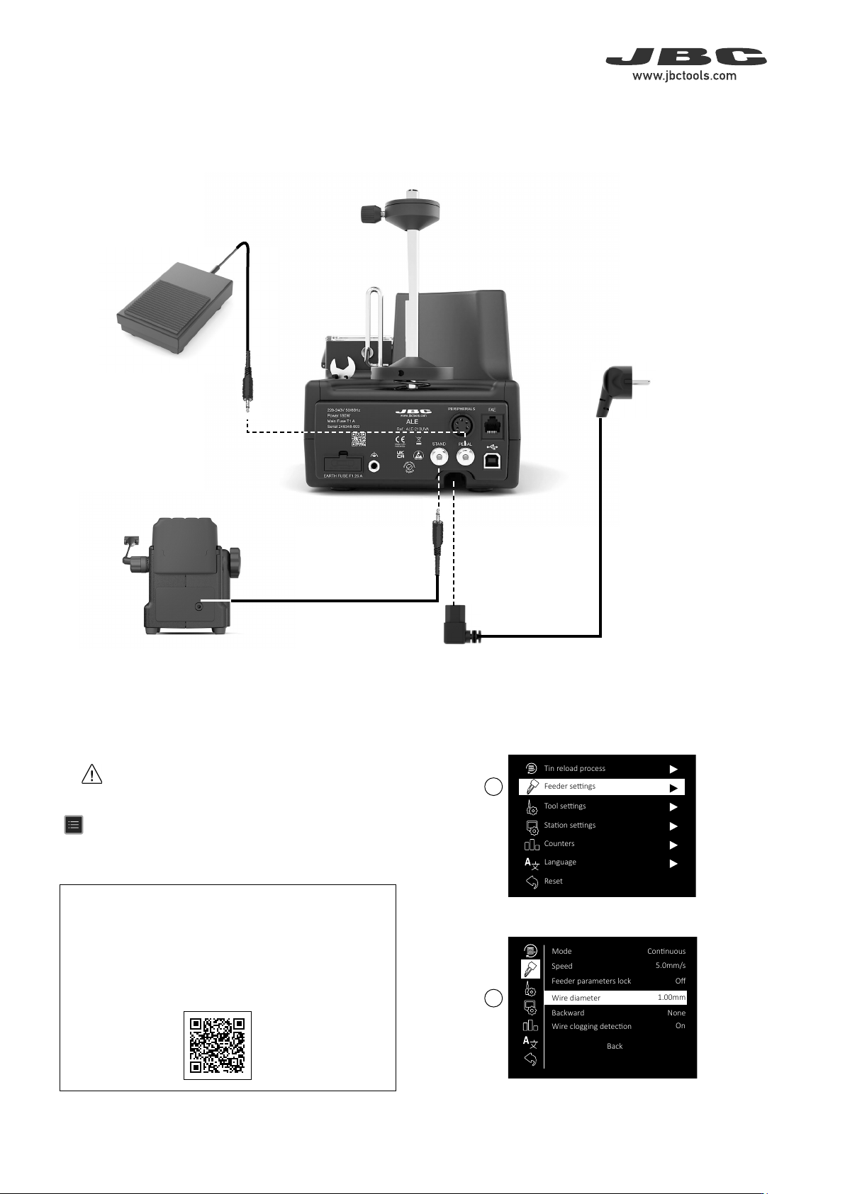
Step 6 Stand, Pedal and Power Cord Installation
At the rear side of the control unit plug in the stand cable, the pedal cable and power cord.
Important:
For correct operation, the diameter of the chosen solder wire
must match that of the guide kit and its components (wheels,
clamps and nozzles) assembled to the ALE.
Guide kits for different wire diameters are available at JBC’s
web site, accessible via this QR code.
Hold up the tool or leave it in the tool holder and switch the station
on. Be careful, cartridge tip will get very hot.
Change the wire diameter by accessing to main menu pressing
, select “Feeder Settings” (1) and then “Wire Diameter” (2) to
adjust the value to the current solder wire diameter.
Power Cord
included in
ALE Control Unit