00196613-0102_AI_LP-Dicke6mmDE+EN.pdf - 第22页
2 Assembly instructions: 6 mm PCB thickness SIPLACE SX1 / SX2 6 mm PCB thickness 06/2009 Edition 22 : Remove the clamping rail in the placement area on all conveyor rails using a size 2 hexa gon socket spanner . 2 2 : In…
6 mm PCB thickness 2 Assembly instructions: 6 mm PCB thickness SIPLACE SX1 / SX2
06/2009 Edition
21
: Use a 10 mm hexagon socket spanner to reduce the height by approx. 2 mm.
: Measure the height of the conveyor at at least 4 points as shown in the picture on page 20. It
must now measure 178.8 +/-0.2 mm.
: Tighten the fixing bolt once more.
2
: Remove the clamping rail and stopper.
2
2
2
2
2
2
2
2
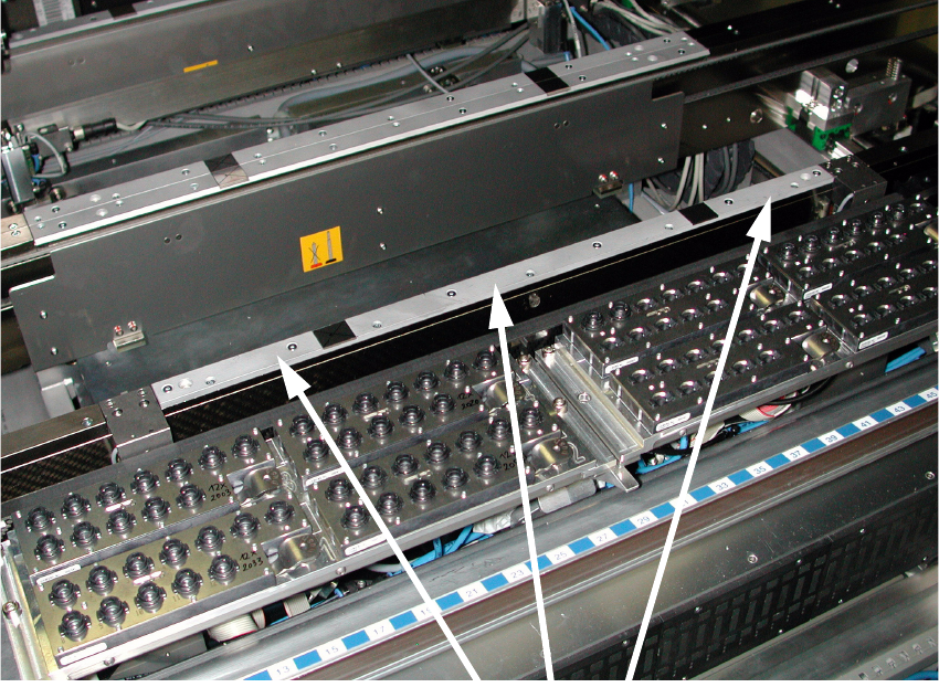
Clamping rails
2 Assembly instructions: 6 mm PCB thickness SIPLACE SX1 / SX2 6 mm PCB thickness
06/2009 Edition
22
: Remove the clamping rail in the placement area on all conveyor rails using a size 2 hexagon
socket spanner.
2
2
: Insert the 460 mm and 519 mm spacer bars between the relevant clamping and guide rails,
and tighten the bolts once more.
2
2
2
2
2
2
2
2
2
2
2
2
2
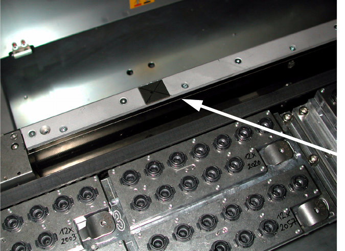
Separate the upper
clamping rail from
the lower clamping
rail 2
6 mm PCB thickness 2 Assembly instructions: 6 mm PCB thickness SIPLACE SX1 / SX2
06/2009 Edition
23
: Make sure that the rails are aligned with the outside of the conveyor rail. To do this, insert the
clamping rail so that the PCB clamping edge is pointing up..
2
2
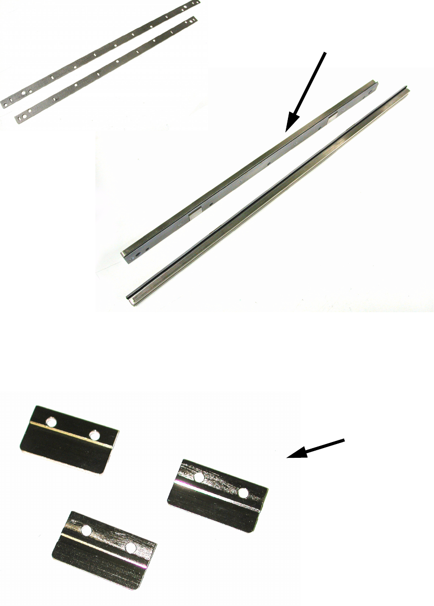
: Remove all the stoppers and insert the 29 mm spacer bar.
Insert the plates beneath each stopper (3 on each conveyor rail).
2
Bars for spacing
Clamping rails with spacing bars inserted
Plates