TM5924.Parts Shape Teach Function.pdf - 第3页
SMT Softw are En gineering Group IM Operations Y AMAHA MOTOR CO., L TD. MDOC-SOFT50225 (1) T ap the [Board] - [M ount] - [T e ach] button to open the mount teach screen. (2) Select the mount data to perform teaching. (3)…
SMT Software Engineering Group
IM Operations YAMAHA MOTOR CO., LTD.
MDOC-SOFT50225
1.
Target model and version
The target model and version are as follows.
Table1.1 Target model and version
Target Model, Software Target Version Remarks
YS100, YS88, YS12 Series,
YG12 Series, YS24, YS24X,
YG300, YSH20, YSC1, YC8
VGOS V3.41 STD R1.000 and later
YSM40 VGOS V4.42 STD R1.000 and later
2. Summary
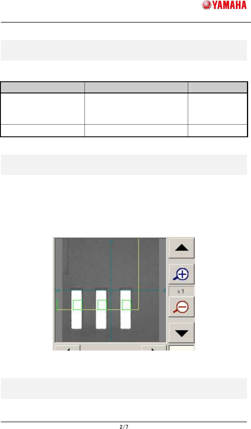
In the parts shape teaching function, the parts definition shape is displayed on the vision
monitor of the mount position teach screen, and the position data at the center of the shape
is obtained. By matching the parts definition shape to the land pattern, this function allows
obtaining a more accurate value even if the parts those are difficult to obtain the center
position by normal teaching.
Fig.2.1 Vision monitor of mount position teach screen
3. Details
The procedure of the parts shape teaching is as follows.
SMT Software Engineering Group
IM Operations YAMAHA MOTOR CO., LTD.
MDOC-SOFT50225
(1)
Tap the [Board] - [Mount] - [Teach] button to open the mount teach screen.
(2)
Select the mount data to perform teaching.
(3)
Move the teaching unit (moving camera) to near the target position using the axis
move button.
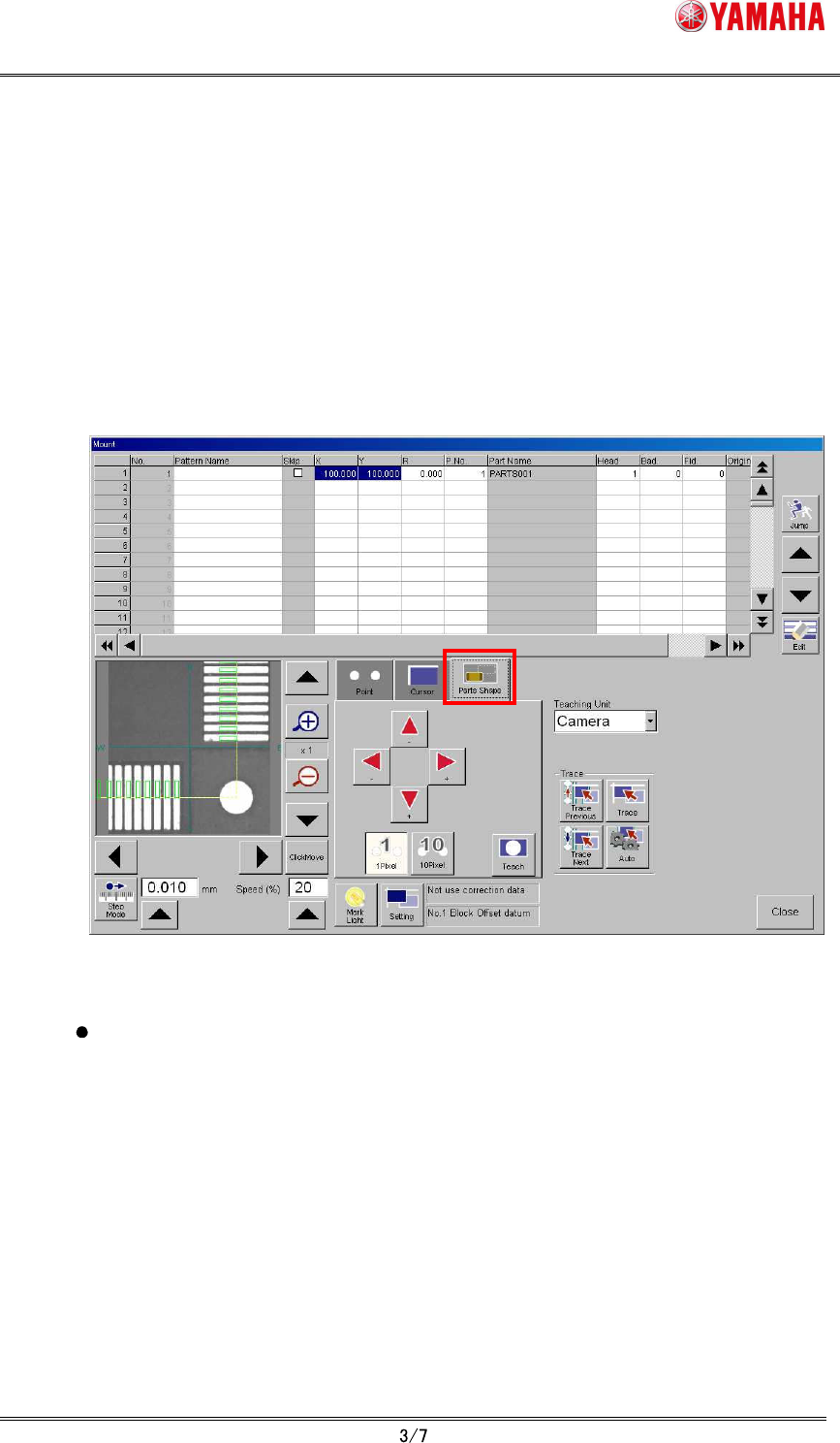
(4)
Tap the “Parts Shape” tab.
Adjust the position of the parts definition shape displayed on the vision monitor using
arrow buttons so that the parts definition shape fit to the land pattern. (Movement
amount is chosen by [1 Pixel] button and [10 Pixel] button)
Fig.3.1 Mount teach screen (Parts shape teach)
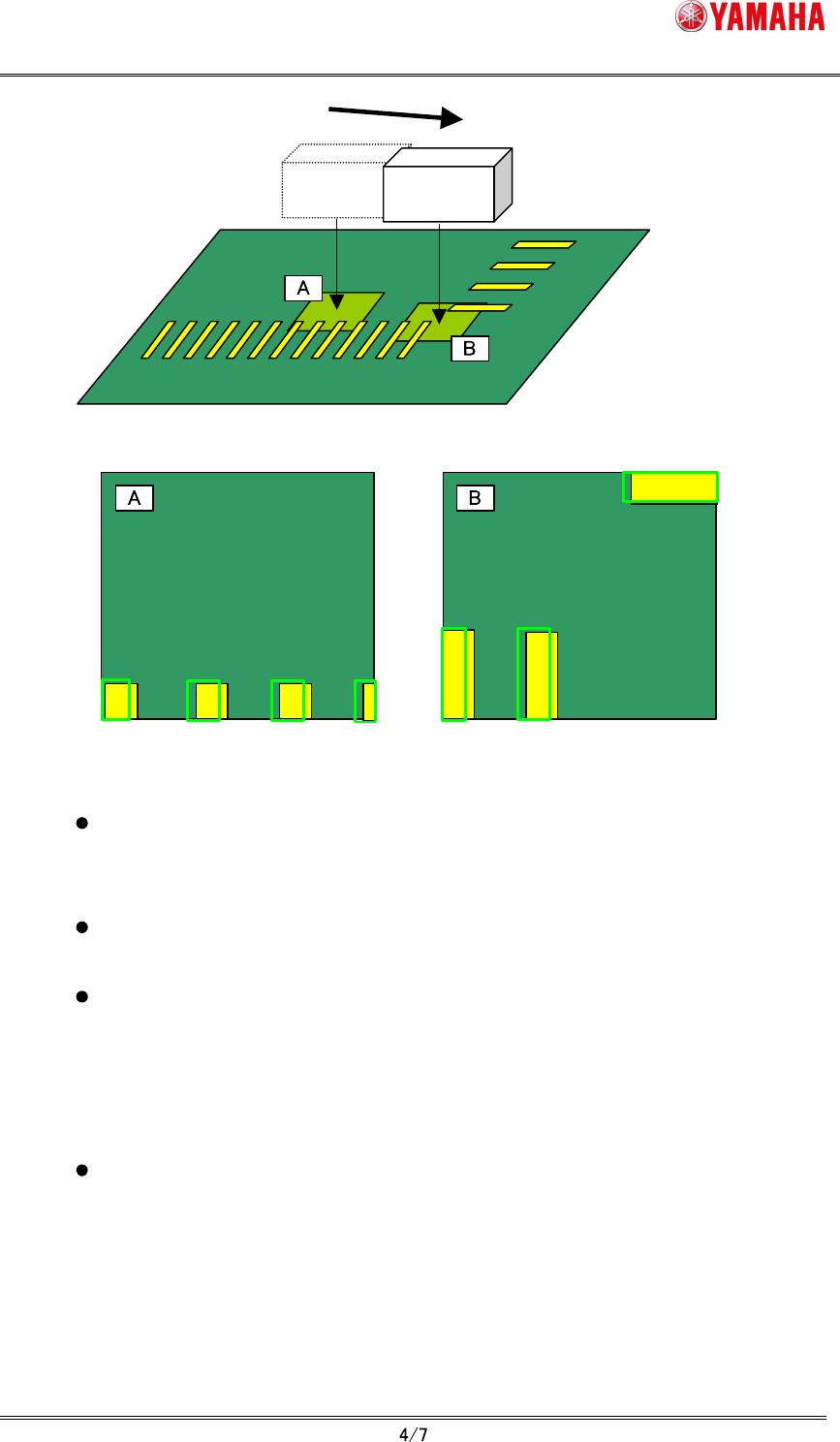
When moving the teaching unit (moving camera), tap "Click Move" button and
change it to pushed state, then tap the position where you’d like to move on the
vision monitor. At this time, the parts definition shape keeps the original
coordinate position.
SMT Software Engineering Group
IM Operations YAMAHA MOTOR CO., LTD.
MDOC-SOFT50225
Moving Camera
When "click move", the parts definition shape remains
displayed at the original coordinates position.
Fig.3.2 “Click move” and the parts definition shape
When “Trace” button is pushed, the teaching unit (moving camera) moves to the
mount position and the parts definition shape is displayed at the center of the
vision monitor.
When the parts definition shape exceeds the vision monitor because parts size
is large, the whole shape is displayed by lowering display magnification.
The parts shape teaching does not support the parts using the specific
recognition algorithm (Refer to chapter 5). In the case of non-support parts,
"Ea12959: Cannot Use Parts Shape Teaching" error is displayed at the timing of
opening "parts shape" tab or selecting grid. In this case, the parts definition
shape is not displayed and the "Teach" button becomes invalid.
The parts definition shape is not displayed when undefined mount data or
mount data that has undefined parts number is selected. The “Teach” button
also becomes invalid.
(5)
Tap “Teach” button.
The center position coordinates of the parts definition shape are input as the teaching
position.