TM5924.Parts Shape Teach Function.pdf - 第5页
SMT Softw are En gineering Group IM Operations Y AMAHA MOTOR CO., L TD. MDOC-SOFT50225 4. Error message list T able4.1 Error message list Error No. T itl e Cause and measure 12959 Cannot Use Parts Shape T eaching The par…
SMT Software Engineering Group
IM Operations YAMAHA MOTOR CO., LTD.
MDOC-SOFT50225
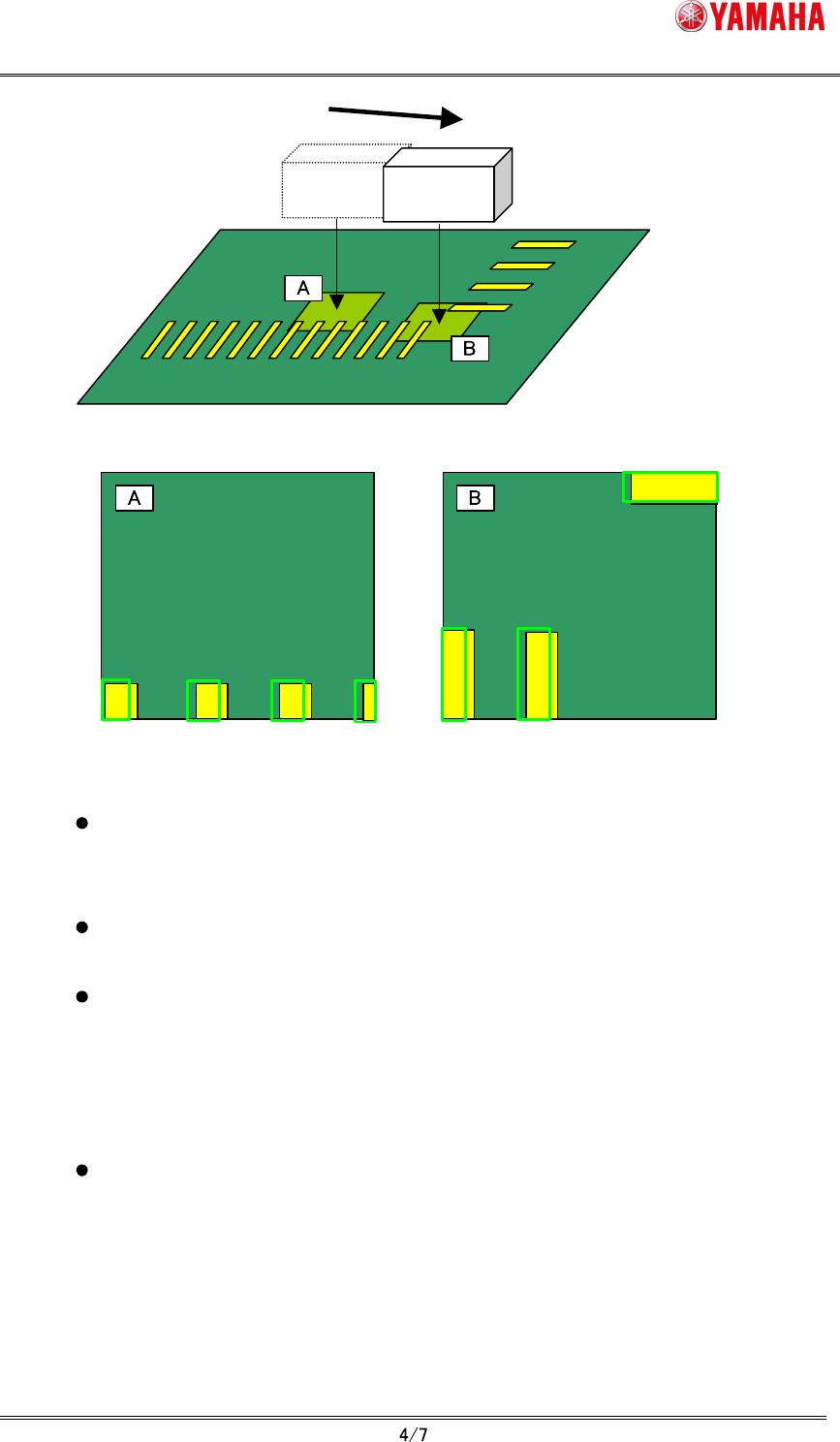
Moving Camera
When "click move", the parts definition shape remains
displayed at the original coordinates position.
Fig.3.2 “Click move” and the parts definition shape
When “Trace” button is pushed, the teaching unit (moving camera) moves to the
mount position and the parts definition shape is displayed at the center of the
vision monitor.
When the parts definition shape exceeds the vision monitor because parts size
is large, the whole shape is displayed by lowering display magnification.
The parts shape teaching does not support the parts using the specific
recognition algorithm (Refer to chapter 5). In the case of non-support parts,
"Ea12959: Cannot Use Parts Shape Teaching" error is displayed at the timing of
opening "parts shape" tab or selecting grid. In this case, the parts definition
shape is not displayed and the "Teach" button becomes invalid.
The parts definition shape is not displayed when undefined mount data or
mount data that has undefined parts number is selected. The “Teach” button
also becomes invalid.
(5)
Tap “Teach” button.
The center position coordinates of the parts definition shape are input as the teaching
position.
SMT Software Engineering Group
IM Operations YAMAHA MOTOR CO., LTD.
MDOC-SOFT50225
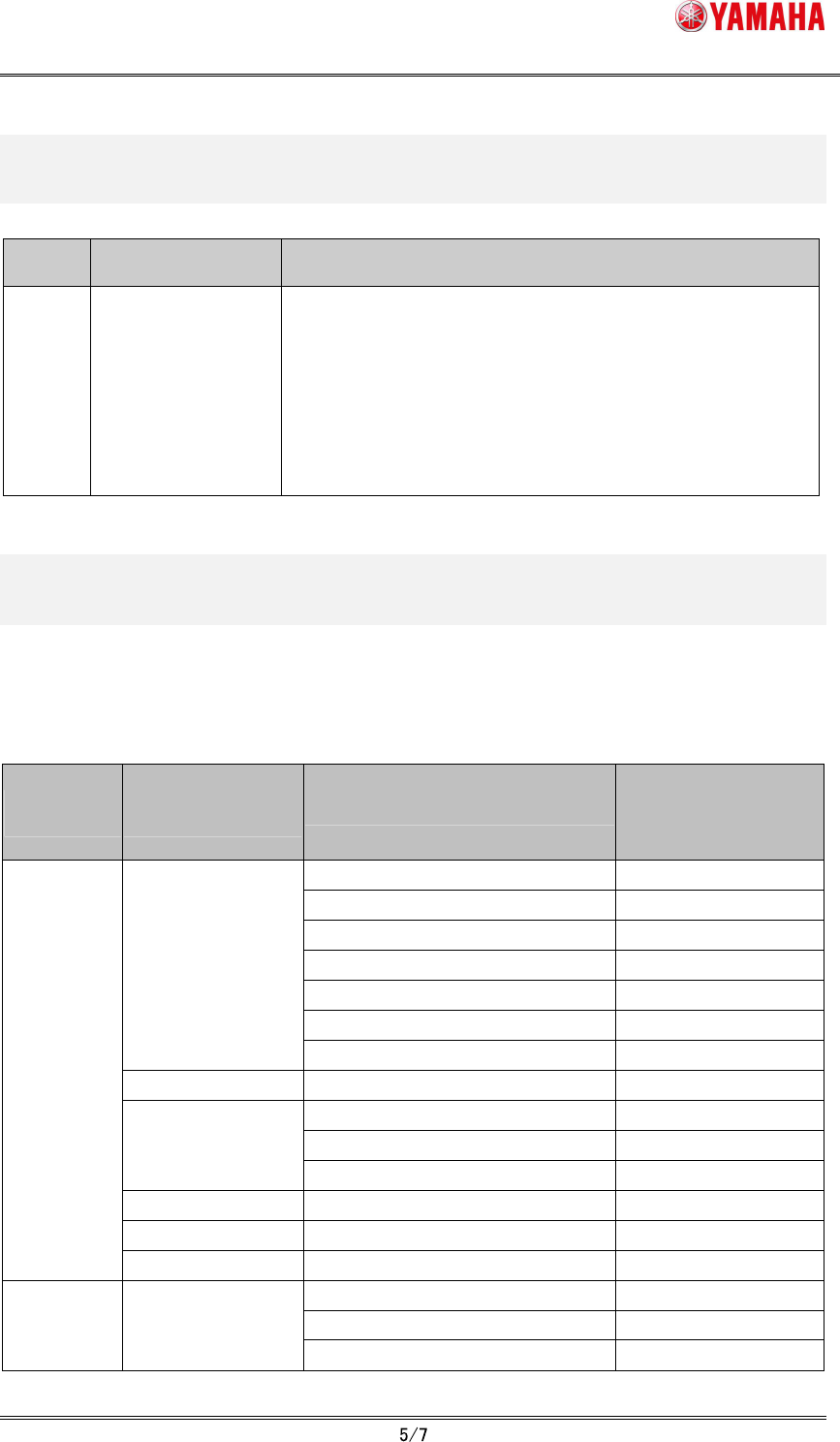
4. Error message list
Table4.1 Error message list
Error
No.
Title Cause and measure
12959
Cannot Use Parts
Shape Teaching
The parts shape teaching does not support the recognition
algorithm used in the parts of this mount data.
Use the point teaching or the cursor teaching.
Mount No.: XXX
Parts No.: XXX
Parts Name: XXX
5. Support / non-support list for every recognition
algorithm
Refer to the following table whether each recognition algorithm supports the parts shape
teaching.
Table5.1 Support / non-support list for every recognition algorithm
Alignment
Group
Alignment
Type
Algorithm
Supported by
parts shape teach
(O: support,
X: non-support)
Normal
O
1: Chamfer Lead
O
2: Check Lead Brightness
O
3: Check Direction
O
4: Check Center Brightness
O
5: Retry Lead Center Search
O
Std.Chip
8: Chip Array
O
Melf Chip Normal
O
Normal
O
12: Size Fitting
O
Bare.Chip
14: Small Bare Chip
O
Cylinder Normal
X
Sp.Chip Normal
O
Chip
Small Chip Normal
O
Normal
O
1: Check Polarity
O
Ball Simple BGA
3: Simple White BGA
O

SMT Software Engineering Group
IM Operations YAMAHA MOTOR CO., LTD.
MDOC-SOFT50225
Normal
O
4: White BGA
O
7: CGA
O
10: Check Direction
O
BGA
12: Ball Circularity Check
O
Normal
O
Simple FlipChip
1: Outside Bump Recognition
O
Normal
O
FlipChip
2: Simple High Speed
O
Normal
O
3: Check Direction
O
2Ends
10: Check Upside-Down
O
Normal
O
Mini-Tr/SOT
4: Check Upside-Down
O
P-Tr Normal
O
Normal
O
1: Side Lead Fitting
O
5: Check Upside-Down
O
6: Check Global Lead Bend
O
7: Direction Check by Lead Width
O
SOP
8: Check Lead Position
O
SOJ Normal
O
Normal
O
1: Side Lead Fitting
O
QFP
4: Check Lead Length
O
Normal
O
1: Side Lead Fitting
O
2: NS Base Search
O
3: WE Base Search
O
PLCC
4: Check Direction
O
IC
OffLead Normal
O
Con-E Normal
O
Con-NSEW Normal
O
Connector
Odd.Con Normal
O
1: Side Lead Fitting
O
2: Long Connector
O
Special
9: Insertion-Component
O
Odd.Chip Normal
O
Normal
X
1: Mark Line
X
2: 2 Objects
X
3: 4 Objects
X
Special
AsMark
4: General
X