NPM Calibration Manual-En.pdf - 第8页
NPM Maint en anc e E di ti on 9.3 Pl ane Com pensati on XY EJM9BE-M B-09M-21 Page 9-7 9.3 Plane Co mpensatio n XY Thi s procedur e i s co mm on to 12-noz zle, 8-nozzl e, and 2-noz zl e heads. Si nce the pl ane-com pensat…
NPM
Maintenance Edition
9.2 Head Camera XY Origin
Page 9-6 EJM9BE-MB-09M-21
7
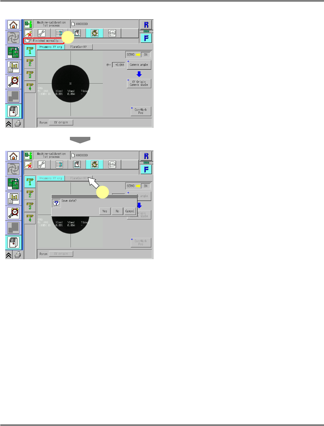
Check that it is successfully complete.
∗
Perform steps 3–7 for also the other table.
8
Press [PlaneCorrXY].
•
When exiting this screen to the other one, you
are always prompted to save the data.
∗
To save the data obtained by the calibration,
press [Yes].
•
If you press [No], the return-to-origin process
is carried out and the data obtained by the
calibration are lost.
•
After the above operation, the next screen is
displayed.
UnitCalibAxisOrigin-03E00
7
UnitCalibAxisOrigin-04E00
8
NPM
Maintenance Edition
9.3 Plane Compensation XY
EJM9BE-MB-09M-21 Page 9-7
9.3 Plane Compensation XY
This procedure is common to 12-nozzle, 8-nozzle, and 2-nozzle heads.
Since the plane-compensation jig is loaded from the upstream process and unloaded to the downstream
process, adjust the width of the upstream and downstream transfer conveyors to that of the
plane-compensation jig.
Remove all support-pins before performing calibration.
For the dual conveyor type, put the conveyor into single lane mode.
( Steps 1 through 7 in “10.5 Single Lane Mode Selection on the Dual Conveyor”.
It is not necessary to attach the board support blocks (for single lane mode).)
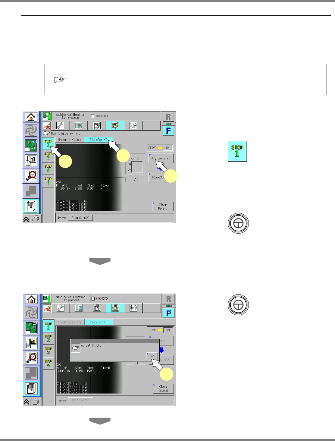
1
Set the plane-compensation jig to the
upstream process.
2
Press .
3
Press [PlaneCorrXY].
∗
Check that no PCBs remain in the machine.
4
Press + [Jig carry in].
•
An error message is displayed if there are
remaining PCBs in the machine.
∗
After removing the remaining PCBs, press
[Jig carry in] again.
5
Press + [Run].
•
The conveyor width is adjusted automatically.
Load the plane-compensation jig.
UnitCalibAxisSurface-02E00
5
UnitCalibAxisSurface-01E00
2
3
4
NPM
Maintenance Edition
9.3 Plane Compensation XY
Page 9-8 EJM9BE-MB-09M-21
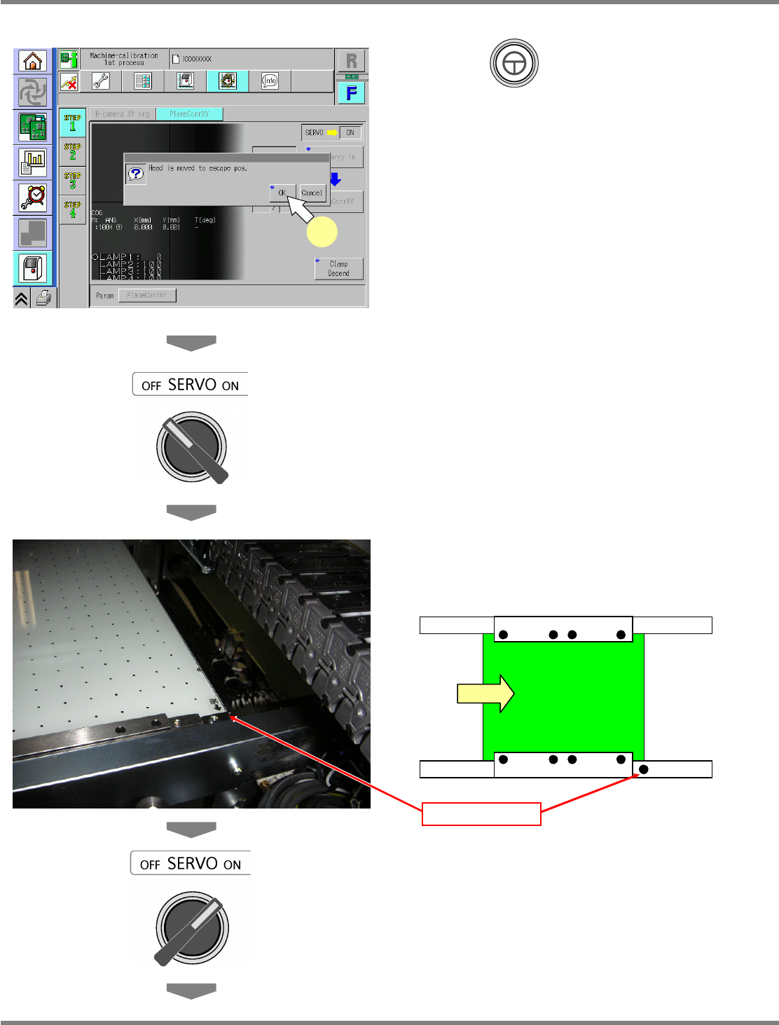
6
Press + [OK].
•
The head moves to the retraction position.
7
Turn OFF the servo switch.
8
Open the safety cover.
9
Set the plane-compensation jig with
its right end fit to the reference mark
on the upper surface of the front rail.
∗
(Common to both the left-to-right and
right-to-left flows.)
10
Close the safety cover.
11
Turn ON the servo switch.
UnitCalibAxisSurface-03E00
6
Reference mark