00195779-0102_UM_D4_SR605_EN.pdf - 第141页
User manual SIPLACE D4 3 Technical data for the machine From software version SR.605.xx 07/2008 EN Edition 3.10 Component trolley 141 3.10.7 Reel holder for the middle t ape reel on 3 x 8 mm S feeder modules Item no. 001…
3 Technical data for the machine User manual SIPLACE D4
3.10 Component trolley From software version SR.605.xx 07/2008 EN Edition
140
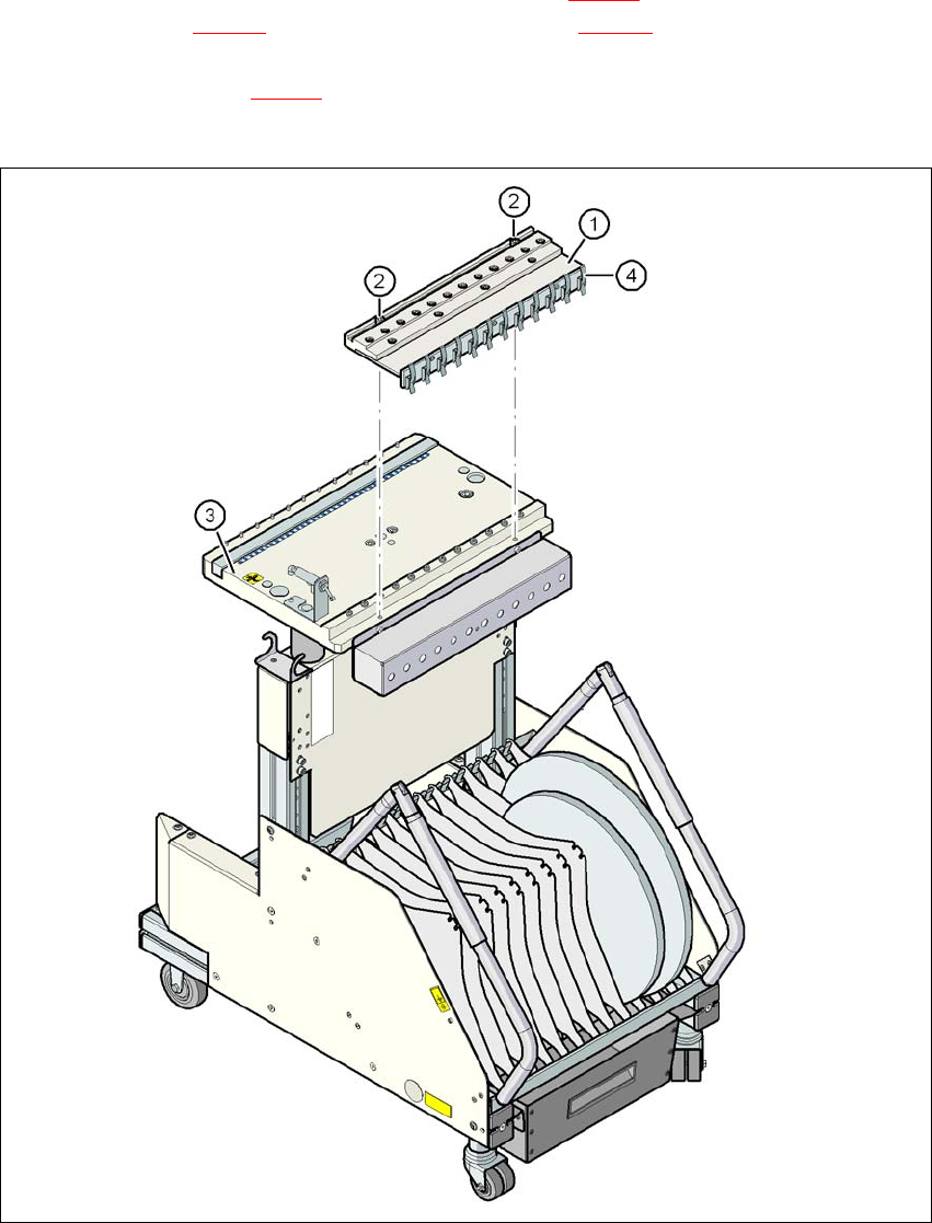
It is easy to fit. The compressed air distributor (item 1 in Fig. 3.10 - 5) is fastened to the component
table (item 3 in Fig. 3.10 - 5
) with two screws (item 2 in Fig. 3.10 - 5). The distributor is then con-
nected to the compressed air supply of the component trolley. The distributor has retaining clips
on the back (item 4 in Fig. 3.10 - 5
). They fix the bulk case feeder modules to the component table
and thus ensure a perfect compressed air supply.
3
Fig. 3.10 - 5 Compressed air supply for bulk case feeder modules
(1) Compressed air distributor
(2) DIN 912 screw, M8x20, 2x
(3) Component table
(4) Retaining clamps
User manual SIPLACE D4 3 Technical data for the machine
From software version SR.605.xx 07/2008 EN Edition 3.10 Component trolley
141
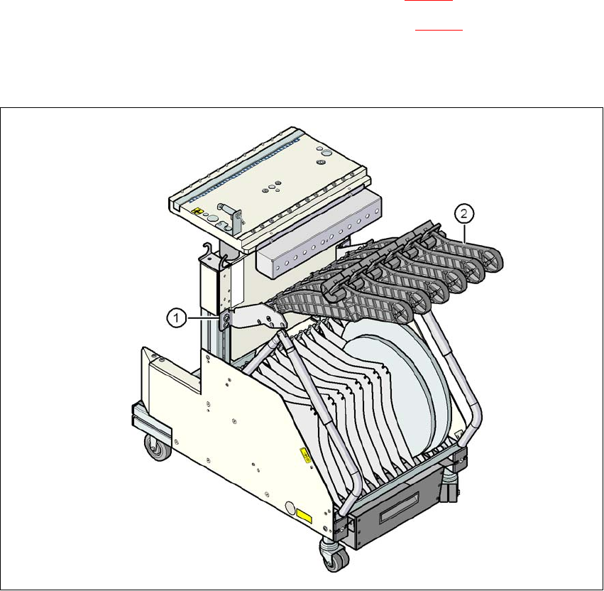
3.10.7 Reel holder for the middle tape reel on 3 x 8 mm S feeder modules
Item no. 00119896-xx Adapter plate, CO trolley D4
Item no. 00141204-xx Tape reel holder, 3 x 8 mm feeder module, V2
Type 3 x 8 mm S feeder modules transport components to the pick-up position on three feeder
tracks. The tape reels for the two outer tracks are located between the dividing plates in the tape
container. The middle tape reel is arranged over the tape reels for the two outer tracks.
For the middle tape reels you will therefore also need:
– 1 adapter plate for holding the tape reel holder (item 1 in Fig. 3.10 - 6
) and
– for every two feeder modules, 1 tape reel holder (item 2 in Fig. 3.10 - 6
)
The adapter plate is fixed to the component trolley with four fillister head screws, and the tape reel
holders are inserted into the square openings in the adapter plate.
Fig. 3.10 - 6 Reel holder for the middle tape reel on 3 x 8 mm S feeder modules
(1) Adapter plate
(2) Tape reel holder
3 Technical data for the machine User manual SIPLACE D4
3.10 Component trolley From software version SR.605.xx 07/2008 EN Edition
142
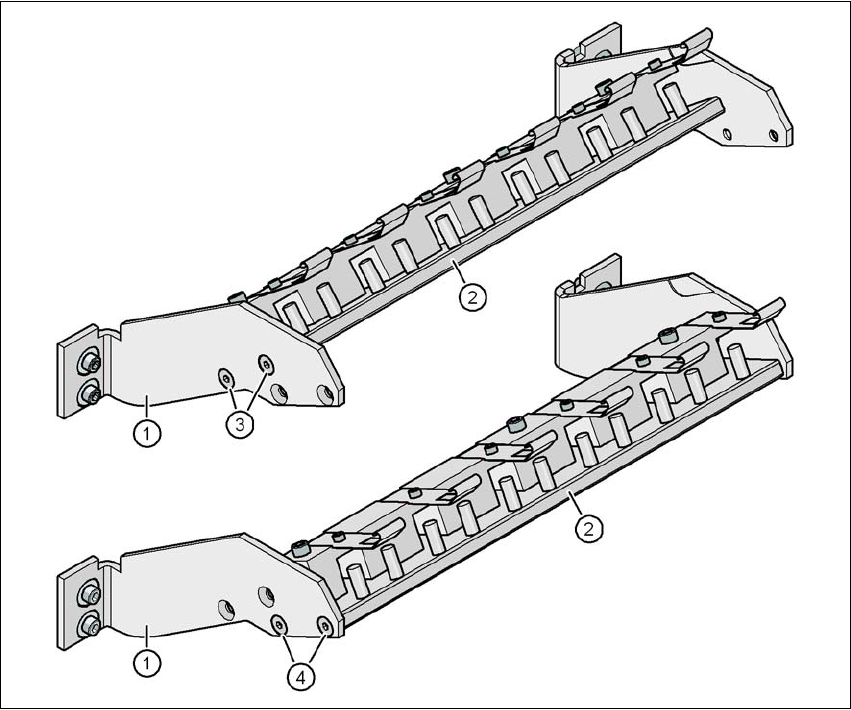
3.10.7.1 Adapter plate assembly position on the adapter plate consoles
There are two different positions on the consoles to fit the adapter plate. The assembly position is
dependent on the implementation of the splice detection option.
3
Fig. 3.10 - 7 Adapter plate assembly position on the adapter plate consoles
(1) Console
(2) Base plate
(3) Assembly position for the base plate without splice detection
(4) Assembly position for the base plate with splice detection