00195779-0102_UM_D4_SR605_EN.pdf - 第143页
User manual SIPLACE D4 3 Technical data for the machine From software version SR.605.xx 07/2008 EN Edition 3.10 Component trolley 143 3.10.7.2 Adapter plate assembly position for 830 mm PCB c onveyor height PLEASE NOTE T…
3 Technical data for the machine User manual SIPLACE D4
3.10 Component trolley From software version SR.605.xx 07/2008 EN Edition
142
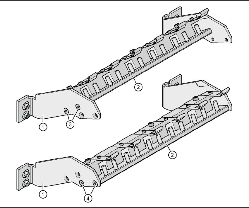
3.10.7.1 Adapter plate assembly position on the adapter plate consoles
There are two different positions on the consoles to fit the adapter plate. The assembly position is
dependent on the implementation of the splice detection option.
3
Fig. 3.10 - 7 Adapter plate assembly position on the adapter plate consoles
(1) Console
(2) Base plate
(3) Assembly position for the base plate without splice detection
(4) Assembly position for the base plate with splice detection
User manual SIPLACE D4 3 Technical data for the machine
From software version SR.605.xx 07/2008 EN Edition 3.10 Component trolley
143
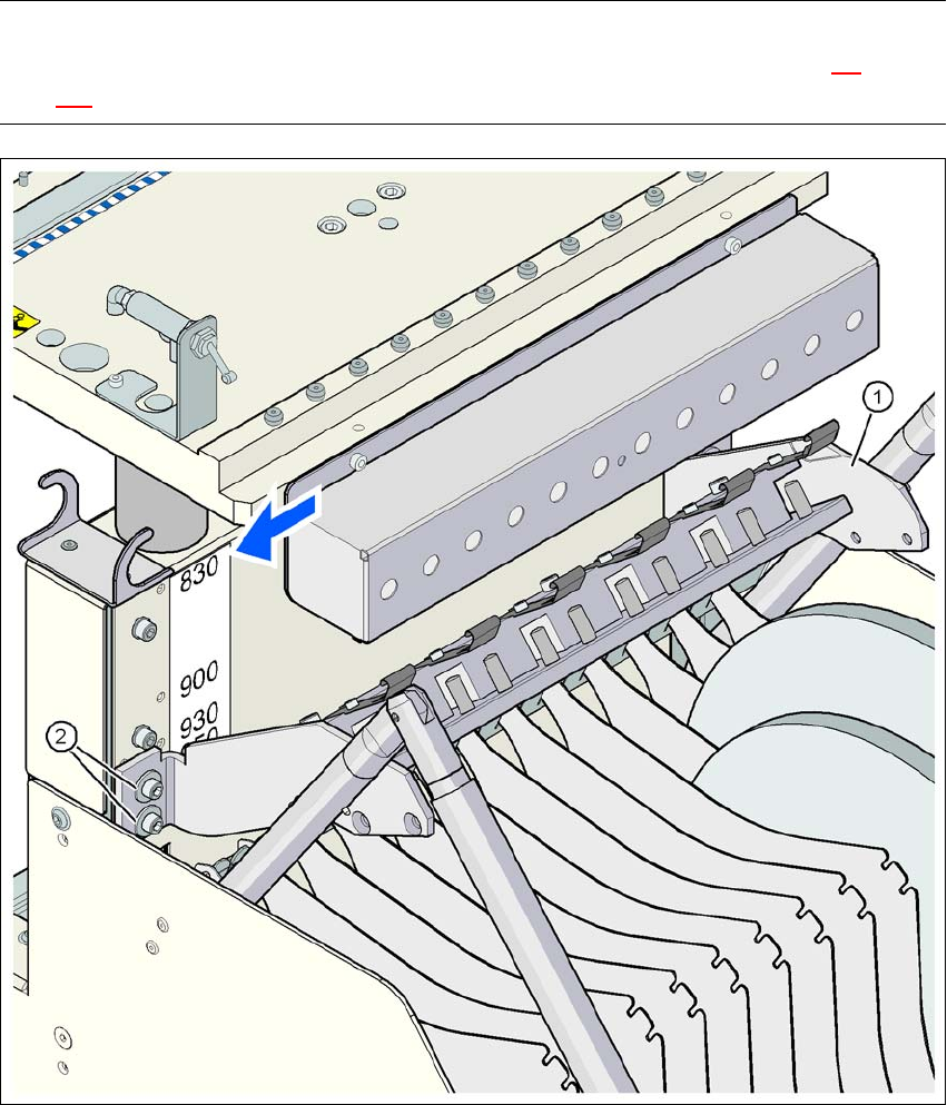
3.10.7.2 Adapter plate assembly position for 830 mm PCB conveyor height
PLEASE NOTE
The procedure for setting the height of the component trolley is described in Section 4.4
, from
page 180.
3
Fig. 3.10 - 8 Adapter plate assembly position for 830 mm PCB conveyor height
(1) Adapter plate
(2) Hexagon socket head screw, M6x20 with washer, 4x
3 Technical data for the machine User manual SIPLACE D4
3.10 Component trolley From software version SR.605.xx 07/2008 EN Edition
144
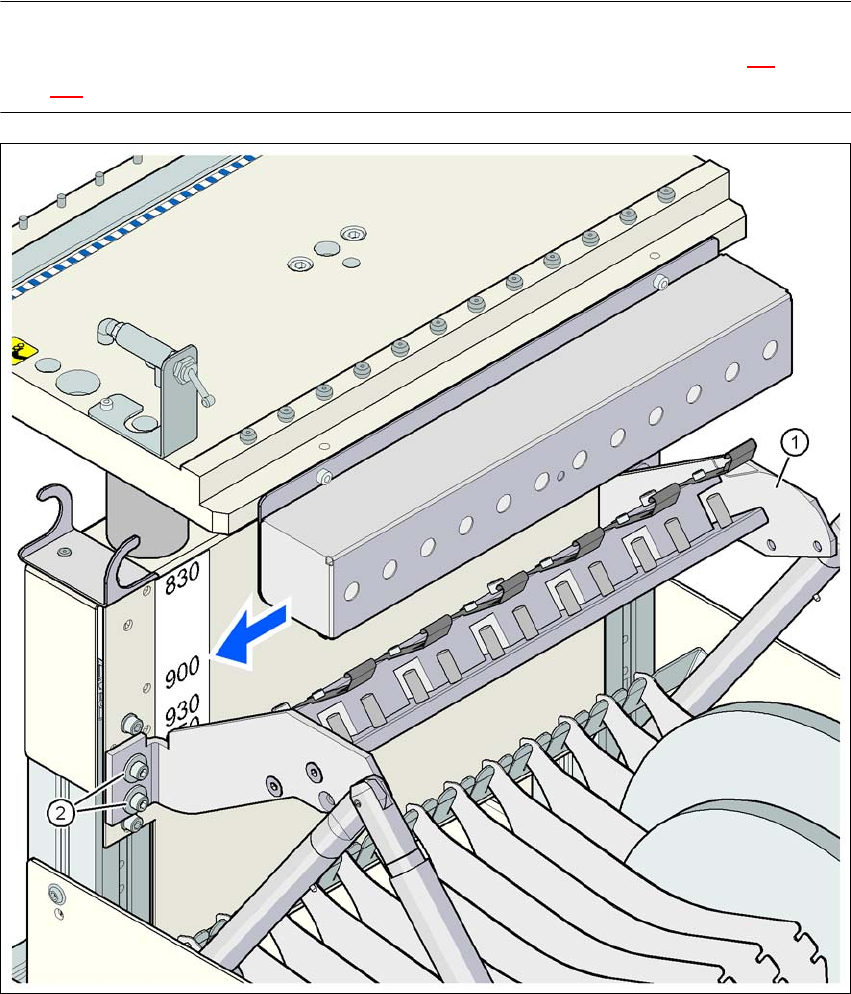
3.10.7.3 Adapter plate assembly position for 900 mm PCB conveyor height
PLEASE NOTE
The procedure for setting the height of the component trolley is described in Section 4.4
, from
page 180.
3
Fig. 3.10 - 9 Adapter plate assembly position for 900 mm PCB conveyor height
(1) Adapter plate
(2) Hexagon socket head screw, M6x20 with washer, 4x