00194547-09_InstallationManual_60103SP4_EN_DE.pdf - 第11页
Installation Manual, Station Software Version 601.03 SP4 Edition 05/2007 BIOS 03.04 T0600304.hex PCB convey or Application 1 05.4E T061054E.hex X X X BIOS 03.24 E0100324.bhx Main/Subdistributor Application 1 03.80 E01103…

Installation Manual, Station Software Version 601.03 SP4 Edition 05/2007
Machine type
Subsystem BIOS / application Version File name
X2 X3 X4
BIOS 03.3F A040033F.bhx
Application 1 01.0E A041010E.bhx
Application 2 / Z 04.6E A042046E.bhx
Twin Head axes
(A364)
Application 2 / DP 04.6E A042046E.bhx
X X
BIOS 03.3F A040033F.bhx
Application 1 01.0E A041010E.bhx
Application 2 / star 04.6E A042046E.bhx
Application 2 / Z 04.6E A042046E.bhx
BIOS / DP
01.04
J0300104.hex
J0400104.hex
C&P20 head axes
(A364)
Application 1 / DP
01.18
J0310118.hex
J0410118.hex
X X X
BIOS 1.04 K0400104.hex
RV head (modular)
Application 1
6.04
K0410604.hex
X X X
BIOS 3.CB K06003CB.hex
RV head (16 bit x serial)
Application 1
2.09
K0610209.hex
X X X
BIOS 03.CB I01003CB.bhx
Twin Head head functions
(2 Prozessor)
Application 1 02.07 I0110207.bhx
X X
BIOS 03.CB I03003CB.bhx
Twin Head head functions
(1 Prozessor)
Application 1 02.07 I0310207.bhx
X X
BIOS
03.CB H01003CB.bhx
C&P20 head
Application 1
01.51 H0110151.bhx
X X X
BIOS
01.01
B0200101.hex
Component table
(CAN, 1MB)
Application 1
01.0B
B021010B.hex
X X X
BIOS
02.01
02.00
B0400201.bhx
B0500200.bhx
Component table (X series)
Application 1
04.0E B051040E.bhx
X X X
BIOS
01.00
01.01
G0200100.hex
G0300101.hex
Tape cutter (CAN 1MB)
Application 1
01.00
01.03
G0210100.hex
G0310103.hex
X X X
10 of 89

Installation Manual, Station Software Version 601.03 SP4 Edition 05/2007
BIOS 03.04 T0600304.hex
PCB conveyor
Application 1 05.4E T061054E.hex
X X X
BIOS 03.24 E0100324.bhx
Main/Subdistributor
Application 1 03.80 E0110380.bhx
X X X
BIOS
03.CD
V05003CD.bhx
VISION modules
Application 1
03.02
V0510302.bhx
X X X
BIOS 02.00 M0200200.bhx
MTC 2
Application 1 02.05 M0210205.bhx
X X
BIOS
02.04
L0200204.hex
L0300204.hex
Digital pressure regulation
valve
Application 1
03.06
L0210306.hex
L0310306.hex
X X X
BIOS 01.02 UA100102.hex
X-Feeders
Application 1 01.44 UA110144.hex
X X X
11 of 89
Installation Manual, Station Software Version 601.03 SP4 Edition 05/2007
3.2 SIPLACE X series hardware components
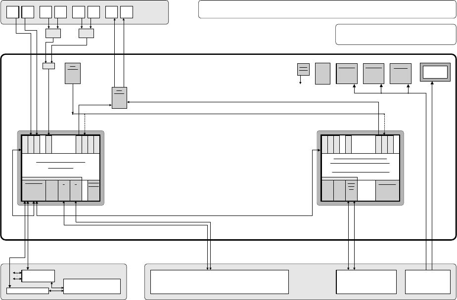
3.2.1 Overview
The following diagram shows the hardware components of the computer system for the X-series
machine types:
Camera system for 2 processing areas with 2 - 4 placement heads
(C&P20/RV head and/or Twin Head) with component vision and PCB position
recognition and up to 2 x complanarity sensor option
(interfaces: sensor > RS485 > USB)
PS
Power supply
Computer unit
Fan unit
40 GB
HD
Manual MUX
switching only
used
(video data
(stationary
images) via hub)
CD ROM drive to
be connected
with the required
computer by
reconnecting the
USB cable
CPU07x-
ZUBLPT
Possibly VMP-HF version with only 1 x VGA
input and 2 x VGA outputs (connect 1 VGA
cable to one of the 2 computers)
PS DC-DC
+-12V / 6A
KSP SV501
PS DC-DC
+3.3V / 20A
KSP NTS50-3
PS DC-DC
+5.0V / 60A
KSP NTS50-5
+24 V
+52 V
Production line
LAN (hub)
Customer LAN
1 2
CAN bus
Decentralized controller
Machine
Y cable
Touch
screen 1
User
interface
Keyboard Y
adapter
Mouse Y
adapter
Video
Multi-
plexer
Touch
screen 2
Keyboard
1
Keyboard
2
Mouse
1
Mouse
2
Monitor
1
Monitor
2
Structure of the computer unit with its interfaces
SIPLACE Pro
programming system
Programming system
and external networks
LAN
Possibly switch
control elements
to USB port
P M 1.6 GHz, ASP 768 MB
Station computer
SMP16-CPU086
+3.6V
Buffer
battery
to
CPUs
Bay
R
E
S
E
R
V
E
SIPLACE X2/X3/X4
series / software: PF IIplus / 2-computer mode
C P C I B u s
LAN HUB .
1 2 1 2 3 4
KSP COM 294
Hot-
link
?
Hot-
link
?
R
E
S
E
R
V
E
CD
KSP
MEM365
L
A
N
C
O
M
A
C
O
M
B
V
G
A
U
S
B
1
U
S
B
2
K
E
Y
B
U
S
B
3
KSP
VMP-HF
40 GB
HD FD
CPCI-MEM371
C P C I B u s
Celeron 650 MHz, ASP 128 MB
Machine controller
SMP16-CPU076 (current configuration)
CAN
1 2
CPCI-
COM
168
R
E
S
E
R
V
E
R
E
S
E
R
V
E
L
A
N
C
O
M
A
C
O
M
B
V
G
A
U
S
B
1
U
S
B
2
K
E
Y
B
Intel M 1600 MHz, RAM 256 MB
SMP16-CPU086 (future configuration)
Fig. 3-1: Hardware components of the computer system for the SIPLACE X series
12 of 89