00197674-01-UM-E-Series-EN-02-2015.pdf - 第30页
1 Introduction User manual SIPLACE E 1.6 SIPLACE Station Programming From software version SC 708.0 02/2015 Edition 30 The SIPLACE Station Programming provides the user at the station with all means that are re - quired …
User manual SIPLACE E 1 Introduction
From software version SC 708.0 02/2015 Edition 1.6 SIPLACE Station Programming
29
1.6 SIPLACE Station Programming
In the SIPLACE Station Programming mode, the user can create a placement program (PCB,
components, component shapes, setup) directly at the placement machine.
The specified fiducials and placement positions are exactly measured by the PCB camera.
After a local optimizing run, the placement process can be started at the station.
In this case, the placement machine can be used independently without a network connection to
a programming system.
For a manual data exchange, the placement programs can be exported from the placement ma-
chine or imported into the placement machine.
In order to implement the station programming mode, the SIPLACE Pro software including the
SQL database is integrated on the station computer. The layout of the SIPLACE Pro GUI has been
adapted to the look and feel of the station software GUI and is displayed as SIPLACE Station Pro-
gramming desktop in the station software.
1 Introduction User manual SIPLACE E
1.6 SIPLACE Station Programming From software version SC 708.0 02/2015 Edition
30
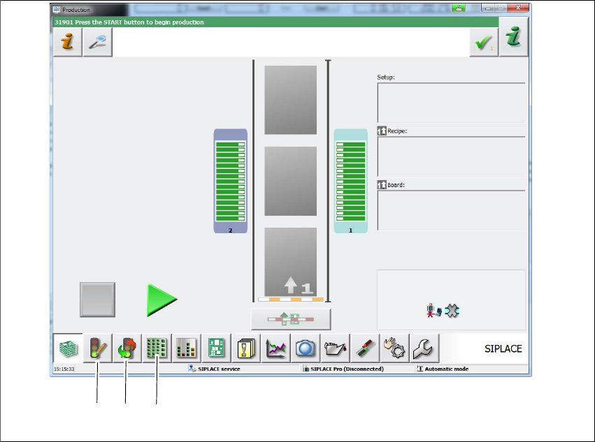
The SIPLACE Station Programming provides the user at the station with all means that are re-
quired for a complete description of the placement program.
1
Fig. 1.6 - 1 SIPLACE Station Programming main view
(1) SIPLACE Station Programming - Job editor
(2) SIPLACE Station Programming - Job control
(3) SIPLACE Station Programming - Teach job
It is possible to work on the description while the placement of another program is still in process.
To ensure an exact specification of the placement positions, fiducials and placement positions can
be taught by the placement machine.
In this process, the semi-transparent outline of the component is displayed above the camera pic-
ture taken by the PCB camera. The outline can then be aligned with the contact points on the PCB.
The specified positions can directly be used and saved in the placement program.
Once the PCB is completely described and taught, it can be optimized and produced at the station.
(1)
(2)
(3

User manual SIPLACE E 1 Introduction
From software version SC 708.0 02/2015 Edition 1.7 Important notes on the user manual
31
1.7 Important notes on the user manual
1.7.1 Contents and filing of the user manual
This user manual contains basic information that must be observed when setting up, operating
and maintaining the machine. The service engineers, qualified staff, operators and users plus sys-
tem owner must therefore read it before commencing installation and commissioning.The instruc-
tions must be kept permanently accessible where the machine is used.
In addition, the user must ensure that the employees have fully understood the contents of the
user manual.
1.7.2 Danger notes
1
1.7.3 Manufacturer's/supplier's liability
We hereby confirm that the contents of this user manual are of a descriptive and explanatory na-
ture only and do not contain any contractual conditions or guaranties. The liability and obligations
assumed by ASM Assembly Systems Singapore Pte ltd can be found exclusively in the relevant
contract agreement concerning the supply of the machine described in this manual. This applies
in particular to all statements regarding performance or service life and the agreed liability for
faults or defects. The provisions of the contract regarding the liability for faults or defect are neither
extended nor restricted by any statements in this user manual.
WARNING
Read the user manual!
Only perform tasks on the machine if you have precise knowledge of the relevant sec-
tion in the user manual.
Observe all warnings, caution notes and hazard notes.
Please also read chapter 2 of this user manual through carefully.