TK30169.Inspection Camera Distortion Correct.pdf - 第5页
SMT Software Engineering Group IM Operations Y AMAHA MOTOR CO., L TD MDOC-SOFT50403 5/7 4. Function Det ails Information necess ary fo r “Inspection Camera Distortion Correct” is acquired at the following timing. …
SMT Software Engineering Group
IM Operations YAMAHA MOTOR CO., LTD
MDOC-SOFT50403
4/7
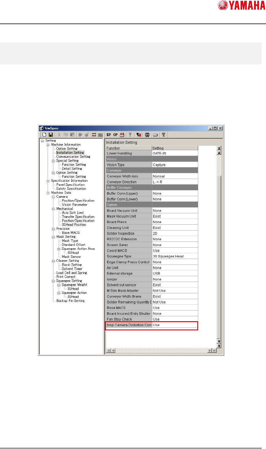
3. Setting Method
Settings to use this function are as follows.
3.1. Machine Setting
Set [Machine Information] - [Installation Setting] – [Option] – [Insp Camera Distortion
Correct] to “Use”.
Fig 3.1 Installation Setting
※ Please make sure to adjust the inspection camera before using the Inspection Camera
Distortion Correct function.
SMT Software Engineering Group
IM Operations YAMAHA MOTOR CO., LTD
MDOC-SOFT50403
5/7
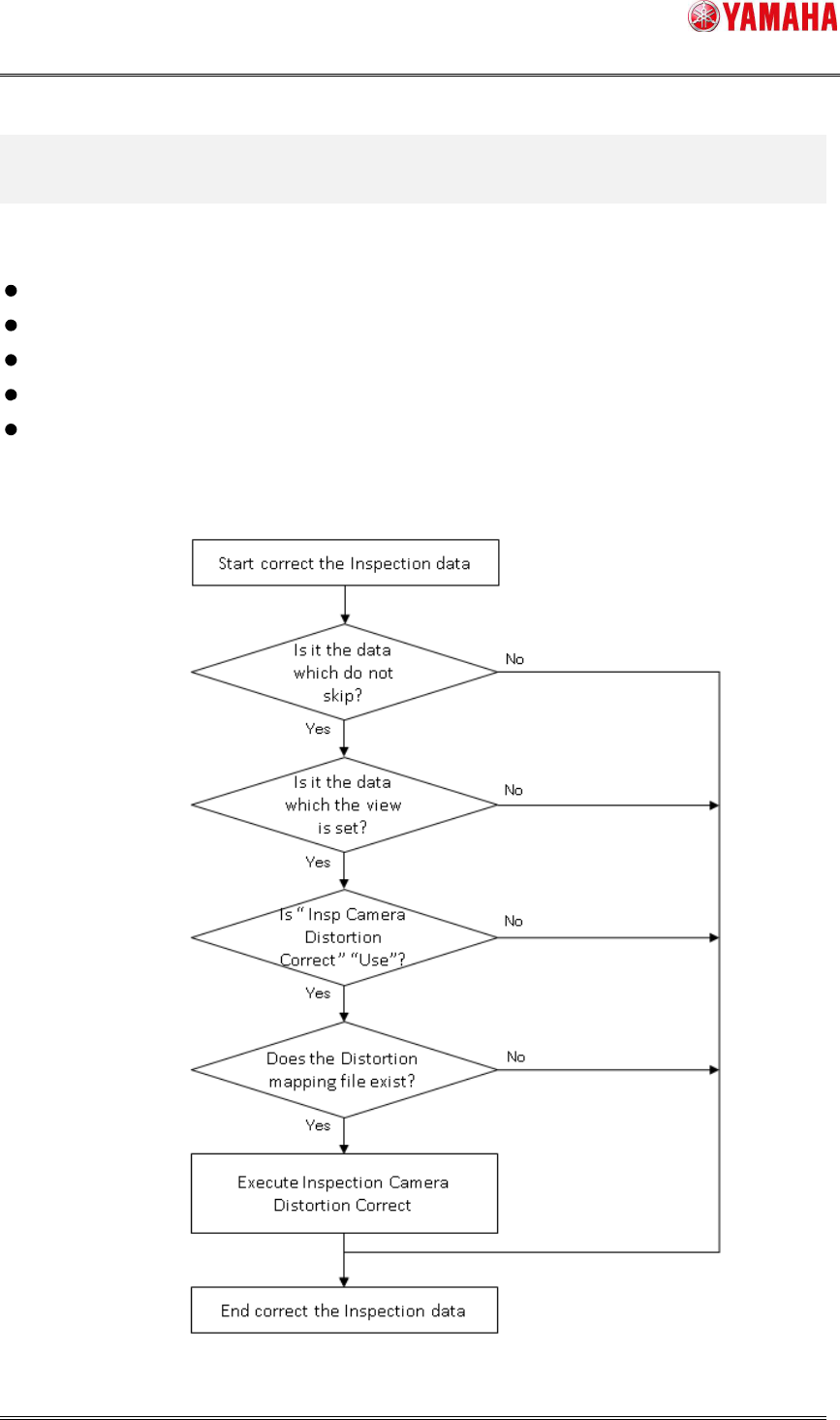
4. Function Details
Information necessary for “Inspection Camera Distortion Correct” is acquired at the following
timing.
When board data is read
At starting auto-running (only when inspection data is changed after board reading)
Test inspection
Adjust View
Object View
The below it the operation flow of Inspection Camera Distortion Correct.
Fig 4.1 Flow Chart of Inspection Camera Distortion Correct
SMT Software Engineering Group
IM Operations YAMAHA MOTOR CO., LTD
MDOC-SOFT50403
6/7
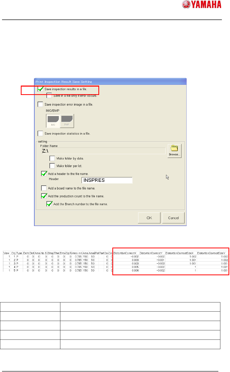
4.4 Log Saving
If you want to save the correction value and corrected size of each inspection data, make
the saving setting on the [Software Setting] – [Model Dependence] – [Print Inspection] –
[Print Inspection Result Save Setting] dialog.
Fig 4.4.1 [Software Setting] – [Model] – [Print Inspection]
Fig 4.4.2 Inspection result file
Table 4.4.1 Items of Inspection Camera Distortion Correct
Alignment Name Description
DistortionCorrectX Distortion correct value X [mm] applied to the target.
DistortionCorrectY Distortion correct value Y [mm] applied to the target.
DistortionCorrectSizeX
Distortion corrected size X [mm]
DistortionCorrectSizeY Distortion corrected size ze Y [mm]
※ When this function is disabled, these items are output with “0”.