00190913-02.pdf - 第25页
Retrofit ting Ins tructi ons Flux Dis penser (Optional) on S IPLACE 80F 4 Edition 08/ 98 Page 9 from 14 3.3.3 Installing the Syringe on the Flux D ispenser Head • Insert the dosing piston into the syringe. • Screw the sy…
Flux Dispenser (Optional) on SIPLACE 80F
4
Retrofitting Instructions
Edition 08/98
Page
8
from 14
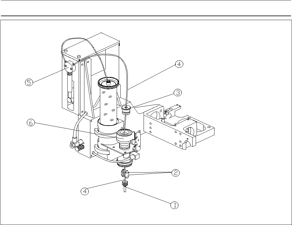
3.3.2 Tubing for Flux Dispenser Head
• Run the long branch of the compressed air hose through the 2 holes in flux dispenser head
• Loosen the clamping force on the pipette tube by backing the centering pipette out about 3 to 4
revolutions.
• Insert the pipette tube into the dosing cylinder from the top.
• Fasten the pipette tube in place by retightening the centering pipette. The pipette tube should project
about 3 mm.
• Run the tubing for flux dispenser head as shown in Fig. 1.
Note
Run the tubes in such a manner that they cannot drag on the hood of the machine.
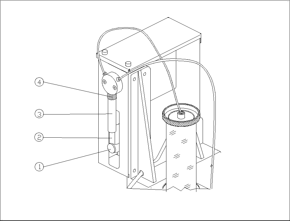
Figure 1 Flux Dispenser Head
− Key to Fig. 1
Centering pipette ô Clamping piece
í Cylinder cover ÷ Dosing hose with pipette tube
û Valve and syringe ø Cylinder
Retrofitting Instructions Flux Dispenser (Optional) on SIPLACE 80F
4
Edition 08/98
Page
9
from
14
3.3.3 Installing the Syringe on the Flux Dispenser Head
• Insert the dosing piston into the syringe.
• Screw the syringe into the valve with the retaining nut.
• Pull the dosing piston down and fasten it in place with the knurled thumb screw.
Figure 2 Syringe
− Key to Fig. 2
Knurled thumb screw ô Dosing piston
í Syringe ÷ Retaining nut
3.4 Installing the Rinsing Tank
• Remove the IC head reject box.
• Remove the reject box holder.
• Install the new reject box holder with rinsing tank holder.
• Insert a centrifugal tube into the rinsing tank holder.
• Slip the brush onto the centrifugal tube.
Flux Dispenser (Optional) on SIPLACE 80F
4
Retrofitting Instructions
Edition 08/98
Page
10
from 14
• Re-install the reject box.
3.5 Converting the Conveyor Control
3.5.1 For Single Conveyor (Stationary Side on Right or Left)
Control unit for PC board handling
• The 4-channel half bridge rectifier PC board in the control unit must be exchanged for the digital 6-
channel half bridge rectifier PC board (00326606-01).
• The 64-terminal base connector is exchanged for the newly coded base connector (00332396-01).
• The 14-terminal connection cable Y0651 is exchanged for the 30-terminal connection cable
(00332439-01). This cable divides into 2 branches at one end. The one with the 14-terminal
connector is run to the machine base via the base plate of PC board handling. The other one runs
on the base plate to terminal point A4/pin 13.
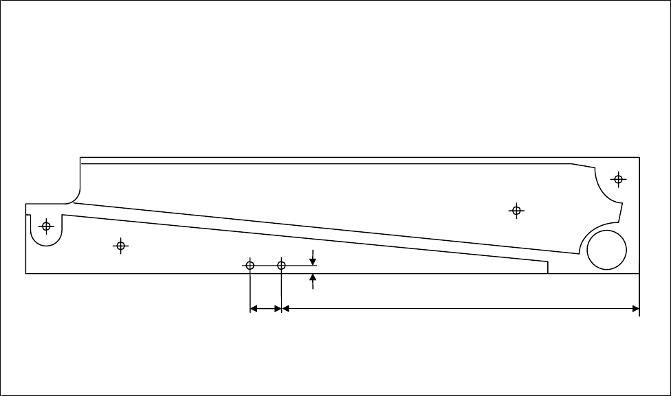
Stationary side cheek of output belt:
• Two threaded holes must be cut in the cheek to attach the light barrier (see Fig. 3).
• The light barrier and the distance plate are both fastened in these threaded holes.
• The light barrier is connected as follows on the base plate:
black core (signal) to terminal distributor A4/pin 13
blue core (ground) to terminal distributor A4/pin 20
brown/pink (br: 24 V= / pink: function high-active) together to terminal distributor A3/pin 10
Figure 3 Holes for Light Barrier
35 mm 300 mm
5 mm
2x M
3