00190913-02.pdf - 第30页
Flux Dis penser (Optional) on S IPLACE 80F 4 Retrofit ting Ins tructi ons Edition 08/ 98 Page 14 from 14 q
Flux Dispenser (Optional) on SIPLACE 80F
4
Retrofitting Instructions
Edition 08/98
Page
12
from 14
• Insert a full storage bin in the holder on the flux dispenser head.
• Turn R26 and mark the position at which LED V21 turns on or off.
• Turn R27 and mark the position at which LED V22 turns on or off.
NOTE
If you cannot turn a diode on, mark the right-hand stop on the potentiometer. However, if a light barrier cannot
be turned off, a fault exists.
• As the final step, each of the 2 potentiometers, R26 and R27, is set in the middle between the 2 marks.
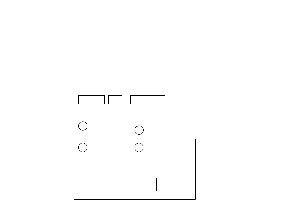
X4 X5 X3
X8
X7
Figure 4 “Component Illumination Board, Flux”
V21
V22
R27
R26

Retrofitting Instructions Flux Dispenser (Optional) on SIPLACE 80F
4
Edition 08/98
Page
13
from
14
3.7 Calibration
Activate the option flux applicator in the menu Miscellaneous/Machine Config. in SITEST
3.7.1 Distance of Pipette Tube <-> Component Camera Revolver Head
• Slip the centering pin onto the pipette tube.
• Press the sealing compound onto a PC board and move the board into the center conveyor.
• Teach the flux dispenser head to a position over the sealing compound and press the centering pin down
into the sealing compound.
• Record the this X- and Y-position.
• Teach the PCB camera to the centered position over the impression in the sealing compound.
• Ascertain the difference between the current X- or Y-position versus the recorded X- or Y-position.
• Add the camera offset, factoring in the prefix of the result, and enter the value in the appropriate field in
SITEST.
3.7.2 Determining the Rinsing Position
• By manually moving the portal by hand, move the pipette tube to the rinsing position.
• Plug the axis test box onto the X/Y-star axis PC board.
• Read the X- and Y-positions from the axis test box and record their readings.
• Calculate the X- and Y-values of the rinsing position on the basis of the following example:
X- value = (Value of axis test box + Distance between pipette tube and compon. camera offset) x 2.5
= e.g., (214251 digit + 276 digit ) x 2.5
= 536318 µm
Y-value = (Value of axis test box - Distance between pipette tube to component camera offset) x 2.5
= (340255 digit - 103607 digit ) x 2.5
= 534938 µm
• Enter the calculated values in Flux.ma.
DANGER O O O
Perform the following test of the rinsing position with just the “Key-operated switch ON” function, since there is
danger of a crash with the flux dispenser head if the rinsing position is entered incorrectly.
Flux Dispenser (Optional) on SIPLACE 80F
4
Retrofitting Instructions
Edition 08/98
Page
14
from 14
q