00193502-01.pdf - 第22页
Retrofit instructions Short Sleeve 05/2004 Edition 22 Install the two lifting plate s unde r the co llar and the centr ing plate in front . 4 4 Lif tin g pla te Lifting plate
Retrofit instructions Short Sleeve
05/2004 Edition
21
4 Retrofit Instructions
4.1 Hardware Modifications
Set up the 24/32mm feeder: 4
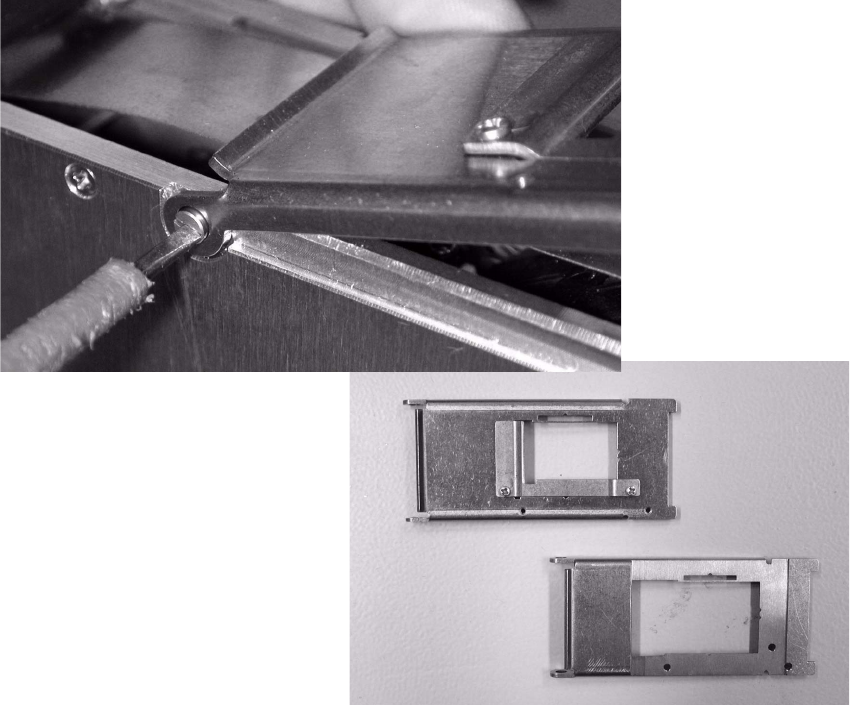
Remove the complete pick up window of the feeder by opening the screws on right an left side,
and screw the new modified pick up window. 4
4
4
In the set up will be a standard 24 or 32mm feeder programmed. 4
4
4
4
4
Retrofit instructions Short Sleeve
05/2004 Edition
22
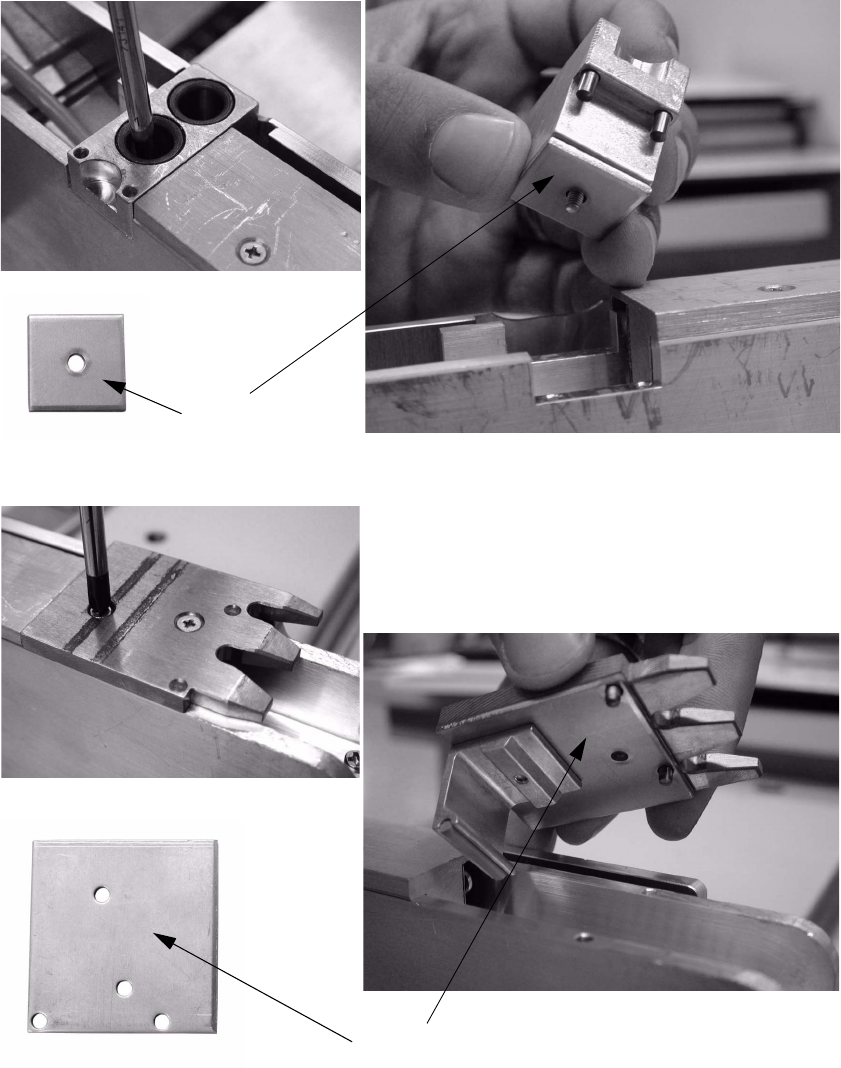
Install the two lifting plates under the collar and the centring plate in front. 4
4
Lifting plate
Lifting plate
Retrofit instructions Short Sleeve
05/2004 Edition
23
4.2 Line Computer Modifications
4.2.1 Changing in the GF Editor
To make a scheduling of the 10.7mm high component possible, the maximum height of the com-
ponent has to be changed to 8.5mm in the editor. The last 2.2mm are added to the tolerances.
E.g. a component with 10.7mm height: type 8.5mm in the standard windows for the component
height and the remaining 2.2mm add to the tolerances. 4
All further component related values stay in the same way and are not modified. 4
Program as a nozzle the special nozzle beginning with number 990 or 790! The sensor type stay
as usual number 12 or 13. 4
Please consider the component size related restrictions at the 12 or 6 star head. 4
12 Segment revolver head max. component size:10mm
6 Segment revolver head max. component size:30mm 4
4.2.2 Optimisation dialog
Due to the modified component height in the GF editor, during the optimisation process the ope-
rator has to take care on following issues: 4
You cannot start a usual optimisation as known from the LCU process. 4
When a component with 10.7mm height is placed on a board, there is a “new” shadow effect crea-
ted which will not exist with the standard sleeve an nozzles. After the placement there is a area
around the high component, where the same machine cannot place any components.
This area has a radius from 5.5mm around the high component (Placement shadow = 0.5 x max
component size + 5.5mm) 4
There fore it is recommended to commit this high component with a restriction to the end of line
machine.
All component inside this shadow has to be omitted from the last machine!
After the programming of the restriction it is possible to star the first optimisation. With this first
result it possible to find out if there are still component inside the shadow effect placed or if the
machine is equipped with 711 or 911 nozzles.
If there are still component inside the shadow or if the last machine is using 711 or 911 nozzles
please star again with programming restrictions on these components. 4
Please refer to process flow OPTIMISATION 4
4