FCS300-R-2LT-H-Manual-1.pdf - 第4页
12. Depress the trigger of the handle assembly (15) to begin fl uid flow. Once fluid begins to spray from the air cap of the va lve (13) continue sp raying until all air is removed from the fluid lines. 13. Adjust the se…
Safety
Due to fluid contents being under pressure eye protection is recommended for
operators. Refer to MSDS sheets on fluid being dispensed for and other precautions.
A grounding wire should be connected to the stainless steel pressure tank to remove esd.
Setup
Refer to assembly drawing 163-03534 for part reference numbers.
1. Connect the system as outlined in the assembly drawing. Being sure the fluid lines
are tightly crimped in the fluid compression fittings and air lines are secure in the
quick connect fittings.
2. Connect main air to the quick connect air fitting of the fluid tank (9) and fitting
(1) of the main air regulator feeding the valve handle.
System Operation
Initial Startup
1. First, be sure the quick air shutoff valve (red handle) of the pressure tank (9) is
turned to the Ext. position so that no air pressure is being supplied to the tank.
Note: Be sure the pressure gauge reads zero before proceeding to the next step.
2. To load fluid into the system, evenly unthread the three handles on top of the tank
until they are loose from the tank top.
Note: The handles will remain connected to the tank lid.
3. Slowly remove the tank lid assembly from the tank body.
4. Place a full bottle of fluid inside the center of the tank with the cap removed.
5. Replace the lid assembly onto the tank, being sure the dip tube that is connected
to the center of the lid inserts into the fluid bottle.
6. Tighten the three handles down evenly for air tight seal.
7. Adjust the pressure on the air regulator (2) feeding the valve handle to 80 psi.
8. Depress the trigger on the handle (15) to cycle the valve open and closed. You
should hear the solenoid actuating inside the handle and will be able to see the
center needle of the spray valve (13) moving back and forth.
9. Adjust the pressure on the atomizing air regulator (20) between 2-3psi for startup.
Note: This pressure will only activate when the trigger of the handle (15) is
pressed.
10. To begin flow of fluid to the valve, open the quick air shutoff valve (red handle)
on the pressure tank (9) and adjust the air regulator to achieve the desired fluid
flow rate.
Note: To begin, start off with a low pressure (5psi.) and increase as necessary.
11. Hold the valve (13) and trigger handle assembly (15) aiming it in a direction
where the fluid can be purged.
12. Depress the trigger of the handle assembly (15) to begin fluid flow. Once fluid
begins to spray from the air cap of the valve (13) continue spraying until all air is
removed from the fluid lines.
13. Adjust the settings and begin to coat.
Adjusting Settings
There are several settings that can be adjusted to fine tune the spray pattern. These
settings are determined by the fluid viscosity, desired pattern width, and coating
thickness.
1. Based on the viscosity, the air pressure regulator of the fluid tank (9) should be
adjusted to supply an adequate flow of fluid to the spray valve.
2. The stroke adjustment of the spray valve (13) should be used to fine tune the fluid
flow rate from the valve.
Note: Refer to the valve manual for further instructions.
3. Adjust the atomizing air regulator (20) to control the volume of air that is used to
break up the fluid and transfer it to the part.
Note: Increasing atomizing air pressure will increase your spray pattern width and
decrease the coating thickness.
Material Change Over
1. First, remove air pressure from the fluid tank (9) by turning the quick air shutoff
valve (red handle) to the Ext. position to dump air pressure.
Note: Allow all of the pressure to drain from the tank before proceeding.
2. When the pressure gauge displays zero, evenly unthread the three handles on top
of the tank until they are loose from the tank top.
Note: The handles will remain connected to the tank lid.
3. Slowly remove the tank lid assembly and wipe fluid from the bottom of the dip
tube.
Note: Fluid may continue to drip from the tube.
4. Remove the empty bottle of fluid from the tank and discard.
5. Remove the cap of the next bottle and place it in the center of the tank.
6. Replace the lid assembly onto the tank, being sure the dip tube inserts into the
fluid bottle.
7. Tighten the three handles down evenly for an air tight seal.
Shut Down Procedure
1. At the end of the day or shift, remove air pressure on the fluid tank (9) by turning
the quick air shutoff valve (red handle) to dump air pressure.
2. Remove air pressure from the regulator (2) feeding the valve (13) and trigger
handle assembly (15).
3. The system can be left unpressurised with fluid still inside it.
Spare Parts
The components listed below are considered wear items and disposable fluid
delivery components that should be kept as spare parts to avoid downtime.
Item Part Number Description Quantity
1 4-ALO
K
-316 ¼” Ferrule Tube Kit 2
2 TFETB01870250B ¼”od UV Safe Teflon Tubin
g
7
3 FCS3-SP Spare Parts Kit for FCS300-
R
Valve 1
Contact your PVA sales representative for pricing
Optional Accessories
To optimize your manual conformal coating system, PVA has developed a few
accessories that can be used to assist the operators.
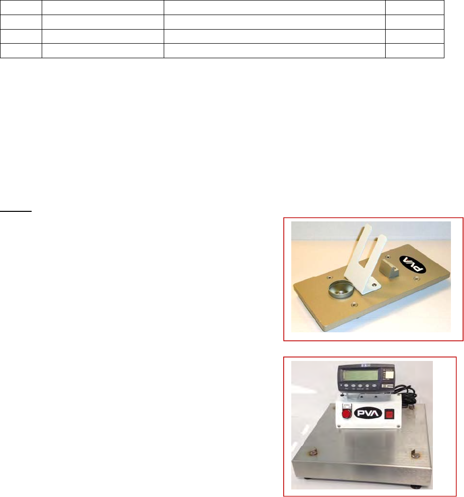
Part #
PV106-S
This stand provides the operator with a place to
set the valve and trigger handle assembly when
it’s not in use to prevent it from tipping. The
purge cup located on the front of the stand allows
the operator to pull the trigger when the unit is in
its holster to clean the nozzle if it has been sitting
for long periods of time.
Low Level
PVA offers a low level scale that can be used
to detect the overall weight of the tank and
material to provide feedback to the operator
before the tank runs out of fluid.
The controller of this scale can be connected
to a PLC or stand alone indicator box.