00195427-02_AI_HeadReconfigKitsD1D2_DE+EN.pdf - 第58页
Assembly instructions Head Reconfiguration SIPLACE D1 / D2 Edition 03/2007 56 2.7.2 Configuring the P&P head with SIPLACE Pro : Go to 'Setup editor' —'Location'—'head t ab' and ente r th…

Assembly instructions Head Reconfiguration SIPLACE D1 / D2
Edition 03/2007
55
2.6 Preparatory measures
: Back-up the machine data for the existing MA configuration
(Hosts.txt, MaData.zip, MaDataInfo.zip, Services.txt)
: Back-up the machine data in SITEST.
Back-up the complete SRCMA directory under a different name.
: Move out the component table or WPC4 if necessary and remove the tape container.
: Remove the waste chute:
Unscrew both screws about 8 mm and push the waste chute out to the back.
2.7 Installing the Pick&Place placement head
This converts a D1 Single head machine (with C&P placement head) to a D1. 2
2.7.1 Configuring the P&P head using the machine configuration wizard
: Start SITEST and select "Settings—Machine Configuration".
: Set the new placement head and the cameras (Standard-camera type 36 / Optional FC-ca-
mera type 25 / IC-camera type 33) and nozzle changers in the machine configuration wizard.
Save the result!
2
: Shut down the station computer.
: Switch the placement machine off at the main switch.
2Detailed instructions for configuring the placement head can be found in the SITEST online help
under Settings / Settings for the Twin Head. 2
Assembly instructions Head Reconfiguration SIPLACE D1 / D2
Edition 03/2007
56
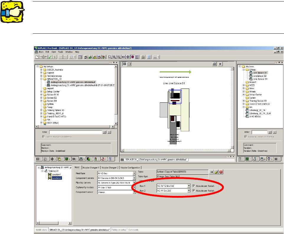
2.7.2 Configuring the P&P head with SIPLACE Pro
: Go to 'Setup editor' —'Location'—'head tab' and enter the C&P placement head.
2
2
: Reoptimize the set-up in SIPLACE Pro.
2The nozzle changer for the P&P head must be configured as row 2 at location 2. 2
For a D1S (with C&P placement head) for a location without placement head, "none" must be
entered for head type and nozzle changer. 2
Assembly instructions Head Reconfiguration SIPLACE D1 / D2
Edition 03/2007
57
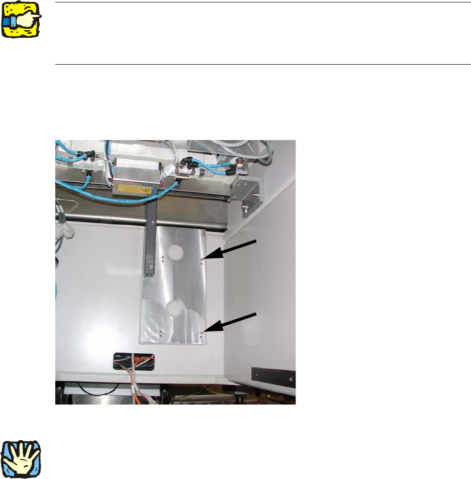
2.7.3 Assembly of component camera stat. P&P (type 36) 32x32 digital,
at location 1
Use two set screws as a mounting aid for the caul (supporting plate for camera calibration) for
mark and camera base.
The hexagon socket side of the set screws must point outwards to enable them to be unscrewed
again. 2
2
: Screw both set screws (DIN913 M6x50 - ST (03005958-)) into the top tapped holes in the ma-
chine frame.
2
Fig. 2.7.1 Set screws (hexagon socket side outwards!)
2
The fiducial plate ("Caul plate for mark") is very heavy! 2
2
2