00195427-02_AI_HeadReconfigKitsD1D2_DE+EN.pdf - 第62页
Assembly instructions Head Reconfiguration SIPLACE D1 / D2 Edition 03/2007 60 : Connect the cable to the camera: – CAN-Bus cable X10au (03050162-) – Hotlink cable (camera bus) X3au (03042343-) – Power supply X4au (030403…
If this is not possible, you must disassemble the camera again and properly move the threaded
pins. No threaded pin can be hidden behind the camera, since this may cause the camera to be
mounted at an angle. 2
Assembly instructions Head Reconfiguration SIPLACE D1 / D2
Edition 03/2007
59
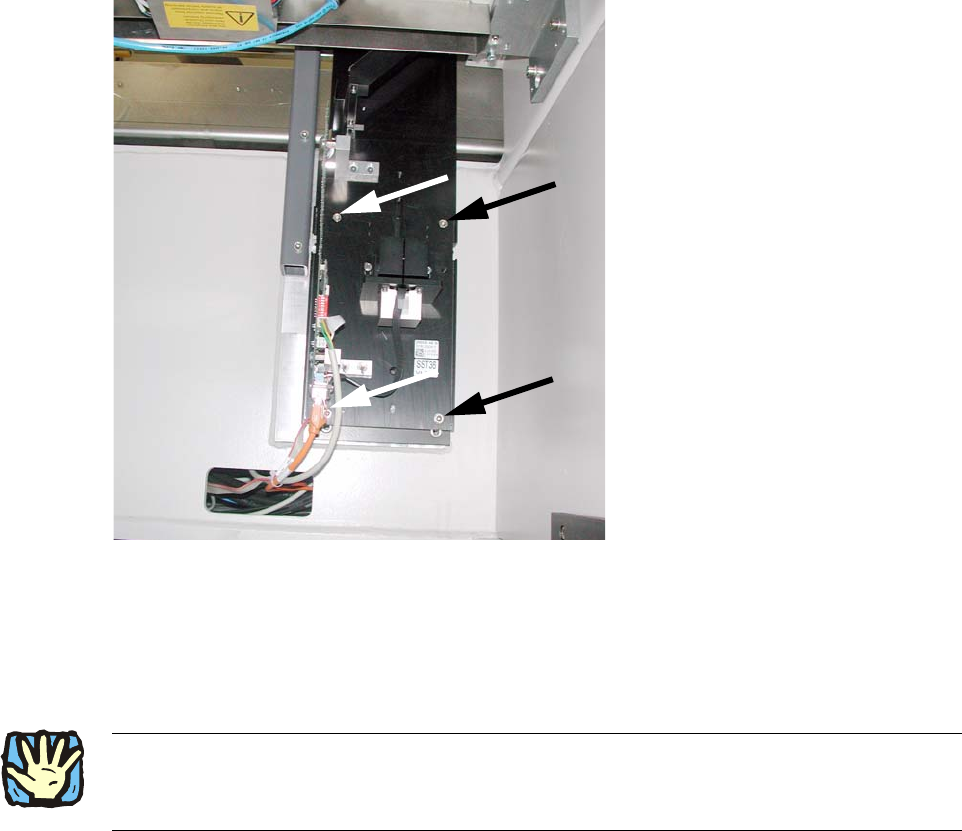
: Also position the camera base on the set screws and fix both with 2 hexagon socket screws
DIN912 M6x35 - 8.8 (00845062-).
2
Fig. 2.7.3 Mount the camera base and tighten 4x
2
: Replace the setscrews with the screws.
2
2
: Pull the three connection cables for the IC camera out of the machine frame
(see 2.7.3).
2
2
2
2
2
2
Assembly instructions Head Reconfiguration SIPLACE D1 / D2
Edition 03/2007
60
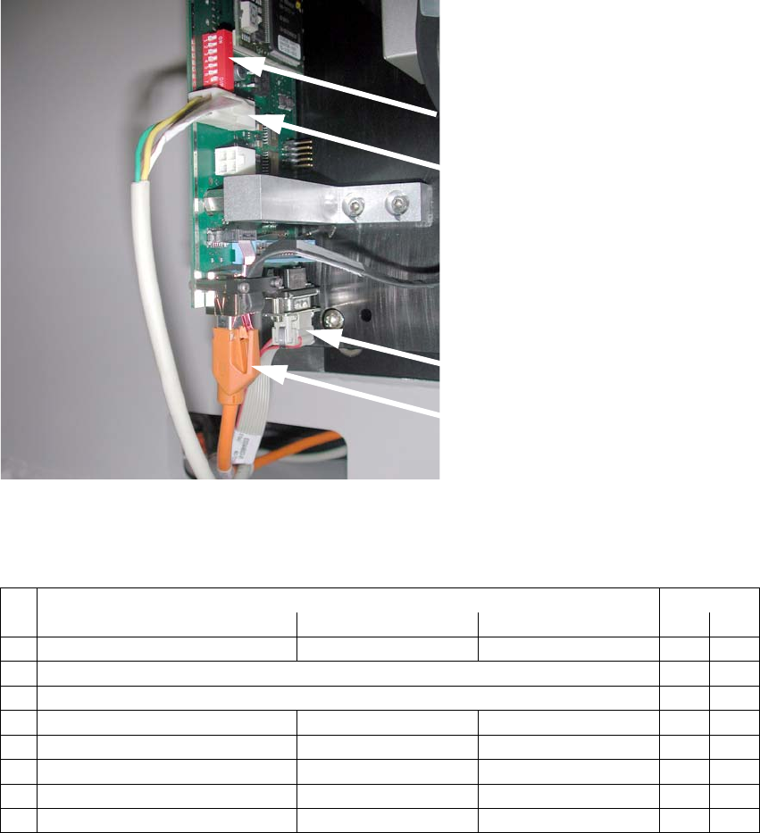
: Connect the cable to the camera:
– CAN-Bus cable X10au (03050162-)
– Hotlink cable (camera bus) X3au (03042343-)
– Power supply X4au (03040347-)
DIP switch
Power supply
X4au (03040347-)
CAN-Bus cable
X10au (03050162-)
Hotlink cable
(camera bus)
X3au (03042343-)
2
Fig. 2.7.4 Connect 3 cables to IC camera
DIP switch configuration:
2
DIP switch Gantry
No. Function ON OFF 1
1 Bootstrap —
2Reset Off
3 Gantry ID 0 Off
4 Gantry ID 1 — Off
5 Code 1 Off
6 CAN terminator with without Off
7 CAN speed = 1 Mbit/s = 500 kbit/s On
8 Camera type IC camera FC camera On
Assembly instructions Head Reconfiguration SIPLACE D1 / D2
Edition 03/2007
61
Flip-Chip Camera:
The assembly and connection of the FC camera is done in the same manner.
See also "Assembly instructions: Flip-chip camera digi
tal 16x16 (SST 25)" (00194554-). 2
2
: Fit the bottom cover with the openings on the camera base and then move it against the rear
panel.
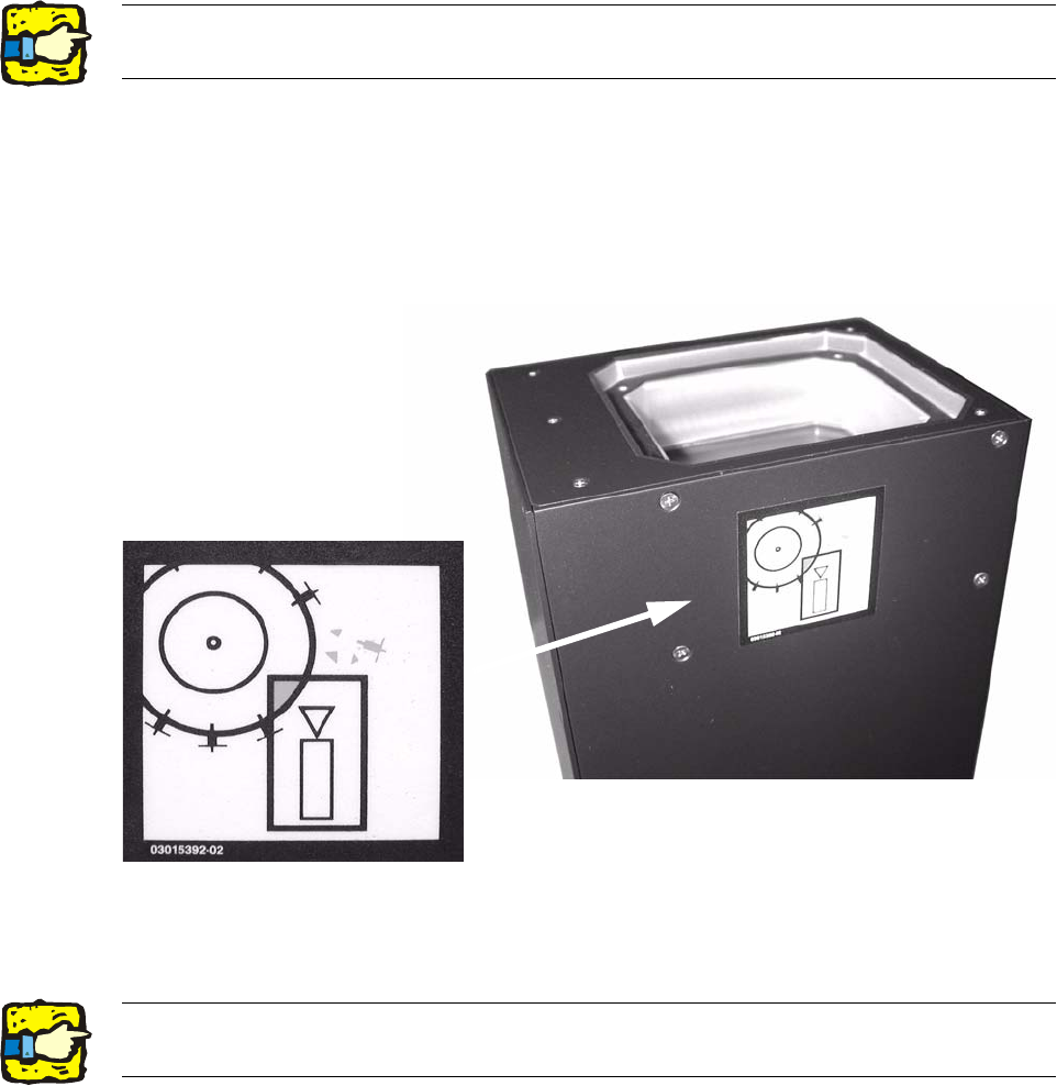
: Use the machine spirit level to check that the camera is aligned horizontally.
: Attach the risk of head crash warning label to the body of the camera (if it is not already at-
tached) as shown below.
2
: Carefully position the lighting unit from above (above the bottom cover) on the camera base
and fix it place with 4 screws (M4x10).
2
2The top edge of the camera should be located about 5 mm below the top edge of the PCB
conveyor. 2