TS5620-user-guide.pdf - 第8页
8 8. MAINTENANCE AND CLEANING Normally, purging the valve with appropriate flush material o r solvent after use is sufficient for cleaning. However some ma terial may cause a buildup in the valve chamber, in this case pe…
6
6. SETUP INSTRUCTIONS
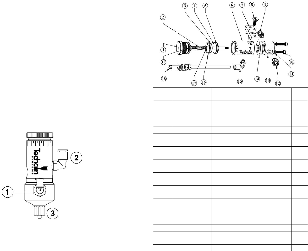
Refer to Figure 4.0
Note: This installation uses Luer lock adapters shipped with the valve. Any
approved material line with ⅛''
NPT connections will work.
1. Connect the fluid reservoir feed tube to the valve inlet port (1).
2. Connect the valve airline to the valve controller or other pneumatic device
that is used to control the valve.
3. Connect appropriate dispensing tip or nozzle to the fluid outlet port (3).
4. Set the valve controller pressure at 70 psi (4.8bar)
5. Set the fluid reservoir pressure. Do not exceed 70 psi (4.8bar)
6. Make sure all connections are tight
7. Place container under the outlet and activate the valve until the fluid flows
steady
The amount of fluid that flows through the valve is determined by:
• Valve open time
• Fluid reservoir pressure
• Dispensing tip size
Figure 4.0
1
3
2
11
SPARE PARTS, CONT - Horizontal Valve
ITEM PART NUMBER DESCRIPTION QTY
1 5620-000-004 End Cap 1
2 TSD1150-40 Spring 1
3 5620-000-006 Anti-Rotate Washer 1
4 5620-000-005 Piston 1
5 TSD1400-016A Piston O-Ring 1
6 5620-000-003 Air Cylinder 1
7 918-000-048 Mounting Bracket 1
8 TSD1106-13 Mounting Screw 1
9 TSD931-58 Inlet Adaptor For TS5620HT/TS5620HU 1
9* TSD931-54 Inlet Adaptor For TS5621HD 1
10 TSD1103-336 Fluid Housing Screw 2
11 TSD1109-53 Flat Washer 2
12 TSD931-60 Tip Adaptor for TS5620HT/TS5620HU 1
12* TSD931-57 Tip Adaptor for TS5621HD 1
13 5620HT-000-001 Fluid Housing for TS5620HT 1
13* 5620-000-001 Fluid Housing for TS5620HU 1
13* 5621-000-001 Fluid Housing for TS5621HD 1
14 5620-000-011 Diaphragm for TS5620HT 1
14* 5620-000-002 Diaphragm for TS5621HD/TS5620HU 1
15 TSD1003-20 Air Fitting, 4mm, Elbow 1
16 TSD1120-11 Retaining Ring 1
17 TSD1109-43 Mylar Washer 1
18 A0100478 Air Hose/Connector Assembly, 4mm 1
19 TSD1400-111A End Cap O-Ring 1
10
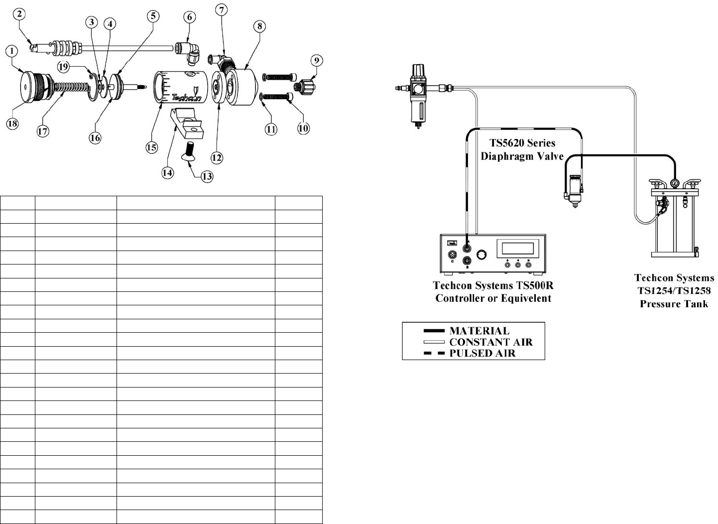
9. SPARE PARTS - Vertical Valve
ITEM PART NUMBER DESCRIPTION QTY
1 5620-000-004 End Cap 1
2 A0100478 Air Hose/Connector Assembly, 4mm 1
3 TSD1109-43 Mylar Washer 1
4 5620-000-006 Anti-Rotate Washer 1
5 TSD1400-016A Piston O-Ring 1
6 TSD1003-20 Air Fitting, 4mm, Elbow 1
7 TSD931-75 Luer Lock Adaptor, Elbow 1
8 5622-000-003 Fluid Housing for TS5622VT 1
8* 5622-000-001 Fluid Housing for TS5622VU 1
8* 5622D-000-001 Fluid Housing for TS5622VD 1
9 TSD931-60 Tip Adaptor for TS5622VT/TS5622VU 1
9* TSD931-91 Tip Adaptor for TS5622VD 1
10 TSD1103-336 Fluid Housing Screw 2
11 TSD1109-53 Flat Washer 2
12 5620-000-011 Diaphragm for TS5622VT 1
12* 5620-000-002 Diaphragm for TS5622VU/TS5622VD 1
13 TSD1106-13 Mounting Screw 1
14 918-000-048 Mounting Bracket 1
15 5620-000-003 Air Cylinder 1
16 5620-000-005 Piston 1
17 TSD1150-40 Spring 1
18 TSD1400-111A End Cap O-Ring 1
19 TSD1120-11 Retaining Ring 1
7
7. TYPICAL SYSTEM SET-UP
Figure 4.0
Figure 5.0
8
8. MAINTENANCE AND CLEANING
Normally, purging the valve with appropriate flush material or solvent after use is
sufficient for cleaning. However some material may cause a buildup in the valve
chamber, in this case periodic and thorough cleaning will be required.
CAUTION: Make sure fluid pressure is released before valve disassembly.
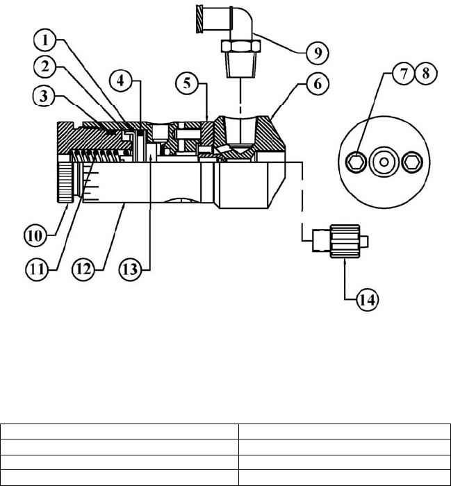
8.1 Cleaning (Refer to figure 6.0)
1. Release fluid pressure
2. Disconnect fluid line
3. Disconnect valve air line
4. Remove the two socket head cap screws (8) from the fluid housing (6)
5. Pull the fluid housing (6) away from the air cylinder assembly (12)
6. Clean Diaphragm (5) and fluid housing (6)
NOTE: Avoid using sharp probes for cleaning. Any nicks or scratches on the
sealing surfaces may cause leakage.
7. Reinstall the fluid housing (6).
8. Align the fluid housing mounting holes with the diaphragm and air cylinder
holes.
9. Reinstall the two socket head cap screws (8). Tighten in accordance with
the Torque specifications chart on page 9.
8.2 To Change the Diaphragm (Refer to figure 6.0)
Tool required: Flat tip screwdriver, Retaining Ring Removal Tool, 7/64”
hex wrench.
1. Remove the two socket head cap screws (8) from the fluid housing (6)
2. Pull the fluid housing away from the air cylinder assembly (12)
3. Remove the old diaphragm (5) by unscrewing it in the counterclockwise
direction.
4. Install the new diaphragm by threading it in the clockwise direction. Make
sure the internal thread on the diaphragm is not stripped or cross-threaded.
5. Hand tightened the diaphragm until it bottoms against shoulder on piston
rod. At this point, do not over tighten or loosen the diaphragm to align the
diaphragm and air cylinder holes.
6. The valve is designed so that the fluid housing can be rotated in 45°
increments to allow for material input/output alignment. For alignment,
insert a small flat tip screwdriver through the hole in the stroke control knob
(10) and engage the piston rod slot. Turn the screwdriver clockwise to
rotate the rod, piston and diaphragm assembly until the appropriate holes are
aligned.
7. Reinstall the fluid housing (6).
8. Align the fluid housing mounting holes with diaphragm and air cylinder
holes.
9. Reinsert the two socket head cap screws (8). Tighten in accordance with the
Torque specifications chart on page 9.
9
8.3 7. To Change or Lubricate Piston O-ring (Refer to figure 6.0)
1. Remove the fluid housing (6).
2. Remove the diaphragm (5).
3. Remove the stroke control knob (10) and spring (11).
4. Remove the retaining ring (1) and anti-rotating washer (2).
5. Remove the piston assembly (13).
6. Replace o-ring (4) if damaged; otherwise lubricate o-ring with Bimba HT-
99, or equivalent.
7. Reinstall piston (13), retaining ring (1) and anti-rotating washer (2).
8. Reinstall spring (11) and stroke control knob (10).
9. Reinstall diaphragm (5) and fluid housing (6).
FLUID HOUSING MATRIAL TORQUE SPECIFICATIONS
Acetal (Delrin®)
14 in lb (1.58 N-m)
UHMW 7 in lb (0.79 N-m)
Teflon®
5 in lb (0.56 N-m)
Figure 6.0