00196642-01 - AI BE-Kamera 38 CPP_de_en.pdf - 第21页
Assembly Instruction 6 Assembly Edition 09/2009 21 In addition to the four screws (M4), th e componen t camera is fixed to the intermediate distr ibutor with an M 2.5 x 4 screw . 6 6 Fig. 6.3.2 Dismantling the placement …
6 Assembly Assembly Instruction SIPLACE X Series
Edition 09/2009
20
X Carefully lift the head out of the locating pins on the head plate.
X If the head mount [03056231-xx] is at hand, fix the placement head onto the head mount.
6.3 Exchanging the Component Camera
6
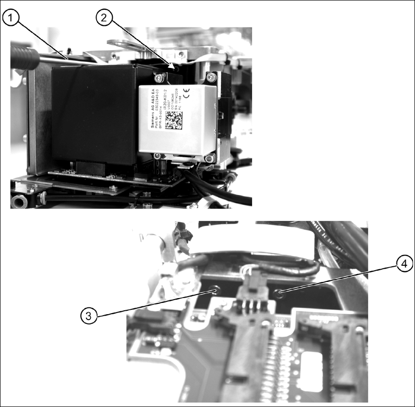
Fig. 6.3.1 Removing the component camera - fixation at the CPP head
X Remove the four fastening screws (items 1 to 4) of the component camera.
Assembly Instruction 6 Assembly
Edition 09/2009
21
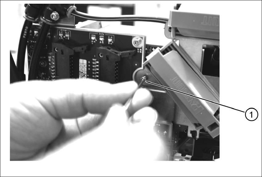
In addition to the four screws (M4), the component camera is fixed to the intermediate distributor
with an M 2.5 x 4 screw. 6
6
Fig. 6.3.2 Dismantling the placement head - safety screw
X Remove the safety screw (1).
X Carefully lift off the component camera.
6 Assembly Assembly Instruction SIPLACE X Series
Edition 09/2009
22
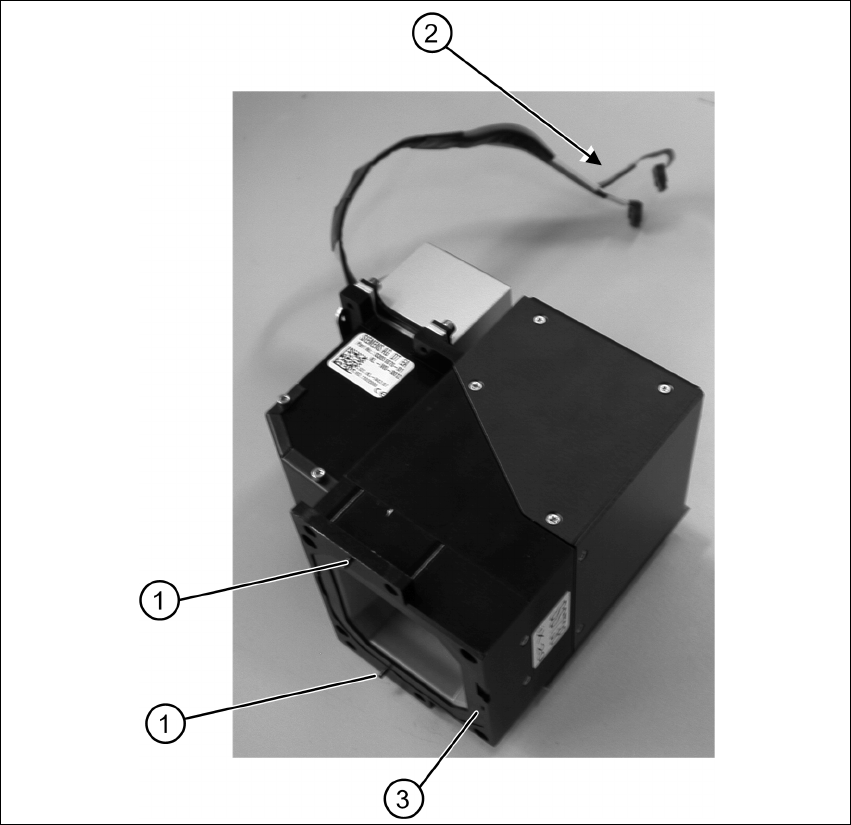
Fig. 6.3.3 Component camera removed - overview
X Make sure that all contact areas on the CPP head and the camera socket (3) are clean.
X Carefully place the new camera onto the CPP head with the two adjustment pins (1) into the
holes until the camera socket lies flush on the contact areas of the CPP head (3).
X Fix the camera with the four fastening screws.
X Fix the camera with the additional safety screw.
X Mount the placement head.