TS1254.pdf - 第4页
4 2. FEATURES • Compatible with a wide range of dispensing fluids • Pressure Relief (Safet y) Valve to ensure safe disp ensing operation • Exhaust valve to depressurize the chamber after operation • One continuous tube f…
10
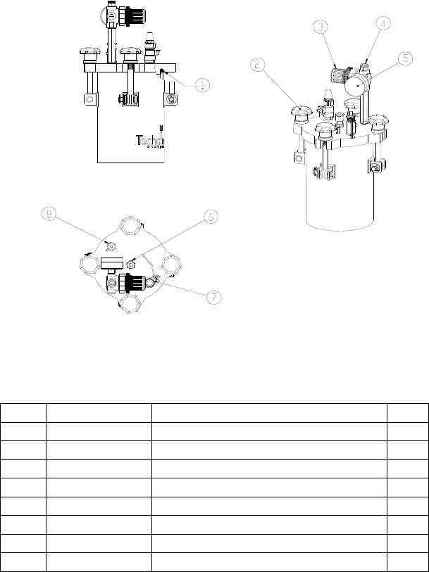
5.3 Parts List
ITEM PART NUMBER DESCRIPTION QTY
1 1254-SIL O-RING, SILICONE M6 X 114 1
2 7054-0030 LOCKING KNOB 4
3 TSD500-37 AIR REGULATOR 1
4 TSD1002-36 FITTING 6MM TUBE X 1/4” NPT 1
5 TSD600-21 PRESSURE GAUGE, 0-100 PSI 1
6 P3000045 FITTING 1/4"NPT X1/4” OD TUBE 1
7 7504-0020 EXHAUST VALVE 1
8 7054-0010 SAFETY VALVE 1
Figure 3 – Parts List
3
1. SAFETY
1.1 Intended Use:
WARNING: Use of this equipment in ways other than those
described in this User Guide may result in injury to persons
or damage to property. Use this equipment only as described
in this User Guide.
OK International cannot be responsible for injuries or
damages resulting from unintended applications of its
equipment. Unintended uses may result form taking the
following actions:
• Making changes to equipment that has not been
recommended in the User Guide
• Using incompatible or damaged replacement parts
• Using unapproved accessories or auxiliary equipment
This User Guide is designed to provide information about the
OK International hardware. Every effort has been made to
make this manual as complete and accurate as possible. There
is no implied or expressed warranty as to the purpose,
suitability or fitness of the information. The information is
provided on an as-is basis. OK International, Inc. reserves the
right to improve and revise its products. This manual specifies
and describes the product, as it existed at the time of
publication.
1.2 Safety Precautions:
Do not apply more than 70 psi (4.8 bar) pressure
Eye protection is required
Do not attempt to open cover lid until air pressure is
released
Cover knobs must be hand tightened ONLY
Secure the pressure Pot to bench top or other stable work
surface
• Check with Factory if unsure about dispensing material
chemical compatibility
• Read the material safety data sheets for special
precautions for the specific material being dispensed.
Wear protective safety equipment as specified in the
material safety data sheets.

4
2. FEATURES
• Compatible with a wide range of dispensing fluids
• Pressure Relief (Safety) Valve to ensure safe dispensing
operation
• Exhaust valve to depressurize the chamber after operation
• One continuous tube for fluid dispensing from container
to the valve
• Use two tubing sizes (1/4” (6mm) and 4 mm)
• Disposable tubing is easy to replace the after dispense
operation
• No material contact with the fluid chamber or tube fitting
• Durable construction
• Cleaning is not required after the dispense operation
3. SPECIFICATIONS
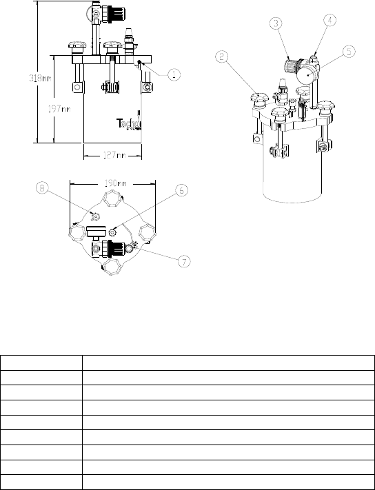
Size: 5”(127mm) x 12.5”(318mm)
Internal Chamber: 4.75”(121mm) I.D. x 6.5”(165mm)
Weight: 10.4 lbs (4.7kg)
Temperature Range: 40 °F (4.4 °C ) – 120 °F (48.9 °C)
Operating Pressure: 70 psi (4.8 bar) max.
Standard Tube Size: 1/4” OD (6mm); include with the unit
Optional Tube Size: 0.157” OD (4mm); need to buy tubing kit
part number =TS1252-4MM…Accessory
kit 4mm fitting and tubing
9
5. ACCESSORIES AND SPARE PARTS
5.1 O-Rings
The Installed O-Ring: The standard O-Ring supplied
on your Pressure Pot is made of Silicone and is intended for
applications with UV adhesive, Lubricants, Conductive and
Non-Conductive Adhesives, and various other compounds.
This O-Ring may be cleaned with Isopropyl Alcohol.
WARNING: Read material safety data sheet for any
solvent prior to use.
Optional O-ring: If your dispense material is not compatible
with Silicone O-ring, you can purchase Viton O-ring
separately
5.2 Fitting and Tubing Kits
There are two tubing sizes can be used with the TS1254
pressure pot, below are part numbers:
The 1254-250PE kit includes:
• Clear PE tube, 1/4” (6mm) OD; Qty = 10’ (3.4m)
• Black PE tube, 1/4” (6mm) OD; Qty = 10’ (3.4m)
• SS Fitting 1/4” OD Tube X 1/4 NPT ; Qty = 1piece
• Nylon Ferrule; Qty = 10 sets
The TS1252-4MM kit includes:
• Clear PE tube, 0.150” (4mm) OD; Qty = 5’ (1.5m)
• Black PE tube, 0.150” (4mm) OD; Qty = 5’ (1.5m)
• SS Fitting 4mm OD Tube X 1/4 NPT ; Qty = 1piece
• Nylon Ferrule; Qty = 10 sets
PART NUMBER DESCRIPTION
1254-VITON O-RING KIT, VITON, TS1254
PART NUMBER DESCRIPTION
1254-250PE ACCESSORY KIT 1/4", FITTING & TUBING (PE)
TS1252-4MM ACCESSORY KIT 4MM, FITTING & TUBING (PE)
8
4.3 Remove old Tubing
1. Pull air pressure regulator knob, turn counterclockwise and
lower air pressure to zero
2. Open Exhaust Valve by turning the lever up (figure 4) to
insure chamber is completely depressurized.
3. Disconnect air supply line if necessary
4. Disconnect fluid tubing from dispense valve
Note: Hold the fluid tubing in vertical position to allow
fluid inside tubing to flow back inside bottle/container.
5. Loosen the four locking knobs slowly and evenly. If
excessive effort is required, insure air pressure gauge reading
is zero
6. Unscrew tube male connector nut completely. Move nut and
ferrule along tubing about 4 inches away from the connector
body on the cover
7. Cut off tubing in between connector body on lid and
nut/ferule. Put the cut tubing with nut/ferrule aside. Take
care to accommodate drainage and spillage at the end of
tubing
8. Wipe off any excess fluid material from the cut-ends of the
tubing’s
9. Remove nut and ferrule parts from the used tube
10. Remove cover from Pressure Pot, while carefully pulling used
tubing half from the container, and set aside. Be careful to
avoid splashing and spilling from the tube end in the material
container/bottle
11. Using a disposable hand glove or tongs, carefully pull the
used-up tube from the connector body on the Lid. Pull tubing
from the inner side of cover plate. Dispose used tubing
appropriately
12. Screw the nut on the connector body. Ferrule parts may be
replaced
13. Disconnect fitting on the dispense end of tubing, and discard
used tube
5
Figure 1- Dimensions
Item Description
1 O-ring
2 Locking Knob
3 Air Regulator
4 Air Inlet port
5 Pressure Gauge
6 Fluid Inlet Port
7 Exhaust Valve
8 Safety Valve