00198460-01_DC_SIPLACE_TX-EditionV2_DE+EN.pdf - 第50页
electric_schematic SIPLACE TX_V2 electric_schematic SIPLACE TX_V2 electric_schematic SIPLACE TX_V2 electric_schematic SIPLACE TX_V2 90012669-010501LE3 Replaced by Low V oltage supply -Fusing Low V oltage supply -Fusing L…
electric_schematic SIPLACE TX_V2
electric_schematic SIPLACE TX_V2
electric_schematic SIPLACE TX_V2
electric_schematic SIPLACE TX_V2
90012669-010501LE3
Replaced by
DC Safety Breaker
DC Safety Breaker
DC Safety Breaker
DC Safety Breaker
Replaced by
Weitergabe sowie Vervielfältigung dieser Unterlage, Verwertung und
Mitteilung des Inhalts nicht gestattet, soweit nicht ausdrücklich zugestanden.
Proprietary Data, company confidential.
All rights reserved
Copying of this document, giving it to others and the use or
communication of the contents thereof, are forbidden without express authority.
Doc. No.
0 1 2 3 4 5 6 7 8 9
Privileged business information.
Do not release
Offenders are liable to payment of damages. All rights are reserved in the
event of the grant or the registration of a utility model or design.
Zuwiederhandlungen verpflichten zu Schadenersatz. Alle Rechte vorbehalten,
insbesondere für den Fall der Patenterteilung oder GM-Eintragung vorbehalten.
Page:
Function: Main Electrics
==ME=TX+03146155/44
drawing number:
03146155-010701LE3
Power Modules
P
ower Modules
Power Modules
Power Modules
GmbH & Co KG
ASM
Assembly Systems
Copyright reserved
Ed.
Original
Pingist
Date
Date
Modification
Appr
13.02.2018
Name
Size DIN A2
Sheet
44
/
5
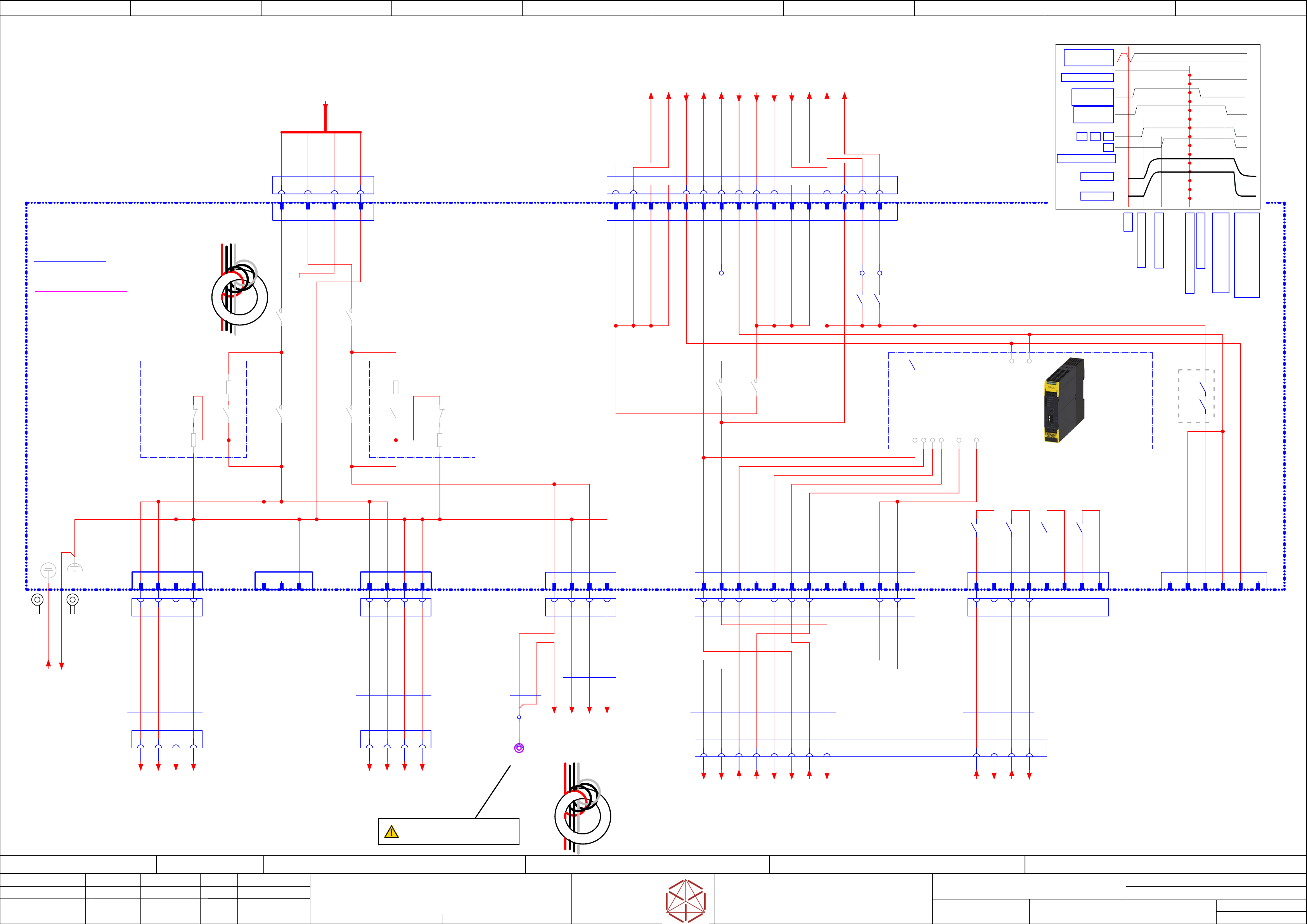
Timing chart
Timing chart
Timing chart
Timing chart
Start
Start
Start
Start
Precharge done
Precharge done
Precharge done
Precharge done
Emergency STOP event
Emergency STOP event
Emergency STOP event
Emergency STOP event
K1,K2, K3, K4 off delay;
K1,K2, K3, K4 off delay;
K1,K2, K3, K4 off delay;
K1,K2, K3, K4 off delay;
Discharge external Cap
Dischar
ge external Cap
Discharge external Cap
Discharge external Cap
-->Power off
-->P
ower off
-->Power off
-->Power off
Safety relais off
Safety relais off
Safety relais off
Safety relais off
Safety relaais off delay
Safety relaais off delay
Safety relaais off delay
Safety relaais off delay
> 100 ms; <180 ms
> 100 ms; <180 ms
> 100 ms; <180 ms
> 100 ms; <180 ms
Precharge start
Precharge start
Precharge start
Precharge start
DC 300 V
DC 300 V
DC 300 V
DC 300 V
DC 160 V
DC 160 V
DC 160 V
DC 160 V
K2
K2
K2
K2
POWER_ENABLE
POWER_ENABLE
POWER_ENABLE
POWER_ENABLE
K1
K1
K1
K1 K4
K4
K4
K4K3
K3
K3
K3
PCC output
PCC output
PCC output
PCC output
delayed
dela
yed
delayed
delayed
PCC output
PCC output
PCC output
PCC output
not delayed
not dela
yed
not delayed
not delayed
EMG_Loop_OK
EMG_Loop_OK
EMG_Loop_OK
EMG_Loop_OK
SW_CTRL_ON
SW_CTRL_ON
SW_CTRL_ON
SW_CTRL_ON
Start
Start
Start
Start
X306: Voltage testing terminal
X306: V
oltage testing terminal
X306: Voltage testing terminal
X306: Voltage testing terminal
Use for testing purpose only!
Use f
or testing purpose only!
Use for testing purpose only!
Use for testing purpose only!
apply 3 windings
near X24A.CSB
use all wires
Note: FELV is for 'Functional Safe Voltage'
Note: FELV is for 'Functional Safe Voltage'
Note: FELV is for 'Functional Safe Voltage'
Note: FELV is for 'Functional Safe Voltage'
P_160
P_GND_1
P_GND_2
P_300
1 2 3 4
-X21.CSB
-
X21.CSB
-X21.CSB
-X21.CSB
FELV_circuit
1 2 3 4
[Power DC 300 V]
-X2p.MGCU2
-
X2p.MGCU2
-X2p.MGCU2
-X2p.MGCU2
1 2 3 4
[Power DC 300 V]
-X2p.MGCU1
-
X2p.MGCU1
-X2p.MGCU1
-X2p.MGCU1
1 2 3 4
-X22B.CSB
-
X22B.CSB
-X22B.CSB
-X22B.CSB
FELV_circuit
-X306
-
X306
-X306
-X306
Voltage
testing terminal
Panel socket 1-pin 4mm
VT SLB4-F 4.8x0.8
VT
VT
VT
VT
DC 160 V OUT
03108631-010301LE3
Connection of negative
Connection of negativ
e
Connection of negative
Connection of negative
potentials 300 V DC
potentials 300 V DC
potentials 300 V DC
potentials 300 V DC
and 160 V DC and MGP is
and 160 V DC and MGP is
and 160 V DC and MGP is
and 160 V DC and MGP is
done here
done her
e
done here
done here
apply 1 winding
near CSB-X19
use all wires
-X24A.CSB
-
X24A.CSB
-X24A.CSB
-X24A.CSB
160 V DC
FELV_circuit
1 2 3 4
-X24B.CSB
-
X24B.CSB
-X24B.CSB
-X24B.CSB
Safety control
signals to FDB
DC42V IN/OUT
1 2 8 9 13 1475 6 10 15 16
3 4 11 12
7x4xAWG16/3xAWG18/5xAWG20
Single Core
03148745
03148745
03148745
03148745 -01
-01
-01
-01
-W10
-
W10
-W10
-W10
BN 18 AWG
WH 18 AWG
GY 18 AWG
GY 18 AWG
YE 20 AWG
YE 20 AWG
GY 18 AWG
GY 18 AWG
YE 20 AWG
YE 20 AWG
YE 20 AWG
BN 18 AWG
Cable connection
FD.A1 160V TX V2
3x18 AWG
Single Core
#03148744-W9.1
VT 18 AWG
VT 18 AWG
WH 18 AWG
VT 18 AWG
WH 18 AWG
Cable connection
FD.A1 160V TX V2
2x18
#03148744-W9.2
A1 B1
-X19.CSB
-X19.CSB
-X19.CSB
-X19.CSB
Power-in
300V, 160V
DYNAMIC D-5200M Receptacle 2x3-pin XY key
TYCO.3-917807-3
B3A3
Machine cable
harness
to Distributor
Safety-loop
& Signals
-X22.DI
-
X22.DI
-X22.DI
-X22.DI
6x0,61
Single core UL/cUL Style
03151246
03151246
03151246
03151246
-W11.1
-
W11.1
-W11.1
-W11.1
B1 B2A1 A2
-X30.CSB
-
X30.CSB
-X30.CSB
-X30.CSB
Safety
Loop Extern
1 2 3 4 5
-X29.CSB
-
X29.CSB
-X29.CSB
-X29.CSB
Safety Loop
& Signals
extern
B5 B6A3 B1A5A1 A6A2
4x0,61
Single core UL/cUL Style
03151246
03151246
03151246
03151246
-W11.2
-
W11.2
-W11.2
-W11.2
A3 B3 A4 B4 A5 B5 A6 B6
PK 20 AWG
YE 20 AWG
YE 20 AWG
YE 20 AWG
YE 20 AWG
YE 20 AWG
PK 20 AWG
YE 20 AWG
YE 20 AWG
YE 20 AWG
YE 20 AWG
6 7 8
YE 20 AWG
4xAWG14
Single core
03151248
03151248
03151248
03151248
-W12
-
W12
-W12
-W12
RD 14 AWG
WH 14 AWG
1
2 3 4
4xAWG14
Single core
03151247
03151247
03151247
03151247
-W13
-
W13
-W13
-W13
1 2 3 4
1 2 3 4
1 2 3 4
RD 14 AWG
WH 14 AWG
RD 14 AWG
WH 14 AWG
RD 14 AWG
WH 14 AWG
#03160454-CSB
#03160454-CSB
#03160454-CSB
#03160454-CSB
Safety control of DC 24V, 42V, 160V and 300 V
Safety Breaker V2
CSB internals see attached document
03112066-020101(CSB)
PCB internals see attached document
03108631-020101ne3
Loop 1-1
1
Loop 1-2
2
Loop 2-1
3
Loop 2-2
4
Loop 3-1
5
Loop 3-2
6
Loop 4-1
7
Loop 4-2
8
-X30
-
X30
-X30
-X30
Safety
Loop external
Loop-closed
A5
Loop2-IN
B1
nc
B2
Loop1_IN
A3
24V-PCC
B5
24V-PCC
B6
-X29
-
X29
-X29
-X29
Safety Loop
& Signals
START_SIG
Start Signal input
A6
nc
A4
nc
B3
nc
B4
OUT2_ND
DC 24V Safety controlled PL=d
3
GND Safety
2
GND Safety
4
nc
1
PPWR-present
5
nc
6
-X31
-
X31
-X31
-X31
Auxiliary
(RFU signals)
-X24B
-
X24B
-X24B
-X24B
Safety
control signals
42V IN/OUT
P300V
1
P300V
2
PGND
3
PGND
4
P160V
1
P160V
3
PGND
2
PGND
4
-X21
-
X21
-X21
-X21
Safety
300V out
-X22
-
X22
-X22
-X22
Safety
300V out
-X22B
-
X22B
-X22B
-X22B
Safety
300V out
-X24A
-
X24A
-X24A
-X24A
Safety
160V out
P300V
1
NC
2
PGND
3
P300V
1
P300V
2
PGND
3
PGND
4
-X19
-
X19
-X19
-X19
Power-in
300V, 160V
B1
P-GND
A1
DC 300V in
24V_S (safety_controlled PL=c)
A2
PWR_ENA (Power enabled)
A1
-K3 -K3 -K4 -K4
-K1 -K1
-K2 -K2
-K3
24V_S
-K3
42V_S
PD160
Precharge/
Discharge
160V
PD300
Precharge/
Discharge
300V
-K4 -K4
Discharge
Precharge
-K4-K4
Discharge
Precharge
-K5
B3
P-GND
A3
DC 160V in
-PE
8
GND Safety
16
K2_Safety_OK
15
K1_Safety_OK
5
24V0 Safety unit
7
PCC_Power_ok
10
DC 42 V fused IN
4
DC 42 V safety-controlled OUT
9
DC 42 V fused IN
2
DC 42 V safety-controlled OUT
1
DC 42 V safety-controlled OUT
3
DC 42 V safety-controlled OUT
6
Power enabled
12
DC 42 V fused IN
11
DC 42 V fused IN
14
24V_Safety_Control
13
DC 24V fussed IN
Safety
Saf
ety
Safety
Safety
Control (K5)
Contr
ol (K5)
Control (K5)
Control (K5)
Safety power supply
GND
Output Power enabled
Input safety loop 1
Output Status safety loop
Input Start
Input safety loop 2
Output Safety loop supply
K2
-K1 -K2
-K5
-FG
-DC160V_S.1
/45.7
-DC160V_S.2
/45.7
-GND160.1
/45.7
-GND160.2
/45.7
-FG.CSB
/42.8
-PE.CSB
/42.4
-42V(F16)_S.1
#03148745-X24B.FD:1 /45.8
-24V(F12)_S
#03148745-X24B.FD:10 /45.9
-PWR_ENA_CSB
#03148745-X24B.FD:4 /45.8
-42V(F16)_S.2
#03148745-X24B.FD:2 /45.8
-24V(F12)
#03148745-X24B.FD:9 /45.9
-24V(F11)_CSB
#03148745-X24B.FD:3 /45.8
-GND_CSB
#03148745-X24B.FD:6 /45.8
-K1_Safety_OK
#03148745-X24B.FD:11 /45.9
-K2_Safety_OK
#03148745-X24B.FD:12 /45.9
-42V(F16).1
#03148745-X24B.FD:7 /45.9
-42V(F16).2
#03148745-X24B.FD:8 /45.9
-CSB_PWR_OK
#03148745-X24B.FD:5 /45.8
-PWR_300V_160V
#03151245-X2.CAP1:1 /43.2
-24V(F12)_S.DI
+03147585/47.3
-S_Start_SSK
+03147585/47.3
-S_Loop1_OUT
+03147585/47.2
-S_Loop2_OUT
+03147585/47.2
-S_Loop1_IN
+03147585/47.2
-S_Loop2_IN
+03147585/47.3
-S_Loop1_ext.in
+03147585/47.3
-S_Loop1_ext.out
+03147585/47.3
-S_Loop2_ext.in
+03147585/47.4
-S_Loop2_ext.out
+03147585/47.4
-DI13_PWR_ENA
+03147585/47.3
-DI0_S_Loop_OK
+03147585/47.3
-DC300.1
==CH+GA/61.1
-DC300V.2
==CH+GA/61.2
-P_GND.1
==CH+GA/61.2
-P_GND.2
==CH+GA/61.2
-DC300V.1
==CH+GA/63.1
-DC300V.2
==CH+GA/63.2
-P_GND.1
==CH+GA/63.2
-P_GND.2
==CH+GA/63.2
electric_schematic SIPLACE TX_V2
electric_schematic SIPLACE TX_V2
electric_schematic SIPLACE TX_V2
electric_schematic SIPLACE TX_V2
90012669-010501LE3
Replaced by
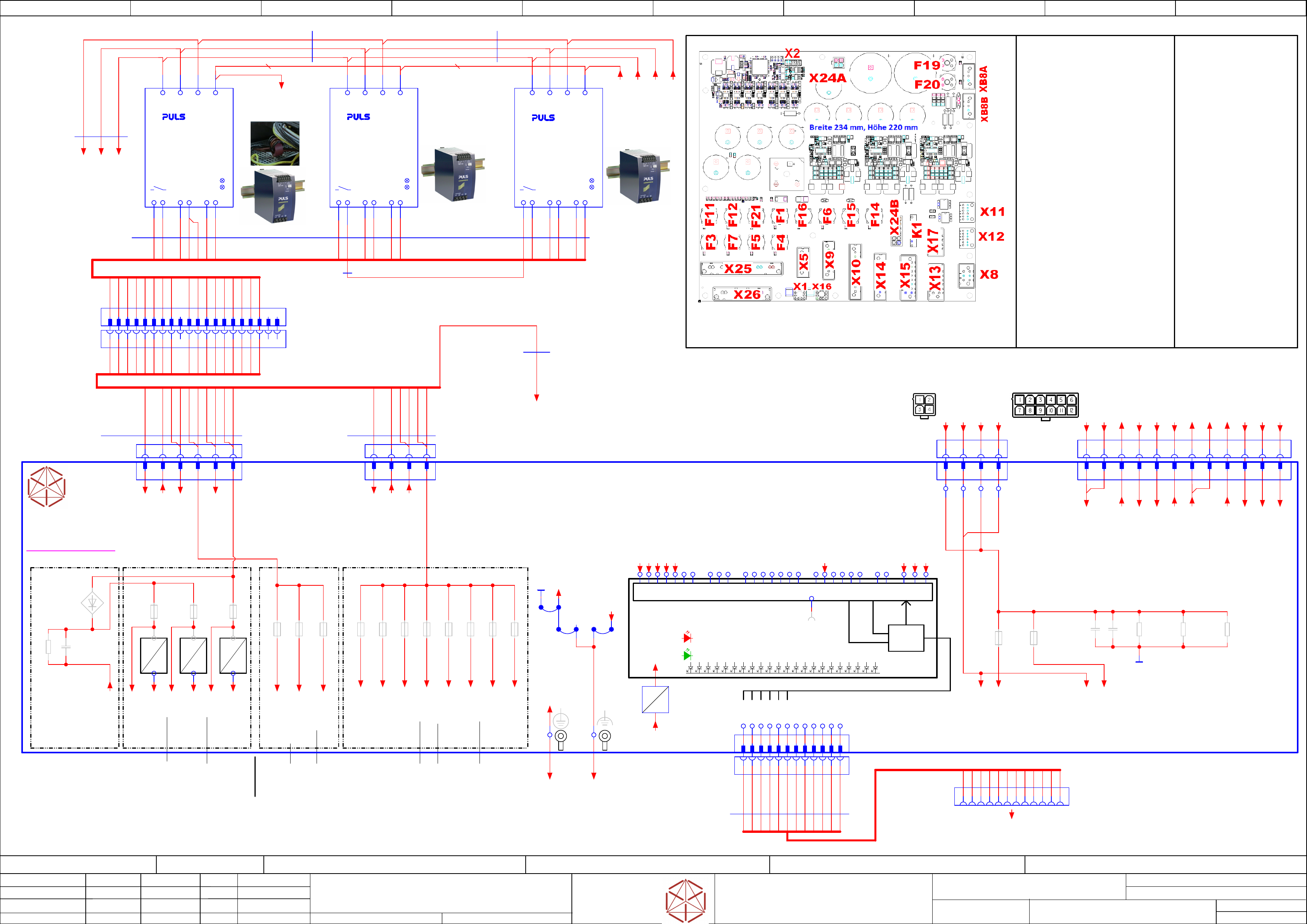
Low Voltage supply -Fusing
Low Voltage supply -Fusing
Low Voltage supply -Fusing
Low Voltage supply -Fusing
Replaced by
Weitergabe sowie Vervielfältigung dieser Unterlage, Verwertung und
Mitteilung des Inhalts nicht gestattet, soweit nicht ausdrücklich zugestanden.
Proprietary Data, company confidential.
All rights reserved
Copying of this document, giving it to others and the use or
communication of the contents thereof, are forbidden without express authority.
Doc. No.
0 1 2 3 4 5 6 7 8 9
Privileged business information.
Do not release
Offenders are liable to payment of damages. All rights are reserved in the
event of the grant or the registration of a utility model or design.
Zuwiederhandlungen verpflichten zu Schadenersatz. Alle Rechte vorbehalten,
insbesondere für den Fall der Patenterteilung oder GM-Eintragung vorbehalten.
Page:
Function: Main Electrics
==ME=TX+03146155/45
drawing number:
03146155-010701LE3
Power Modules
P
ower Modules
Power Modules
Power Modules
GmbH & Co KG
ASM
Assembly Systems
Copyright reserved
Ed.
Original
Pingist
Date
Date
Modification
Appr
07.02.2018
Name
Size DIN A2
Sheet
45
/
5
X8
dU = 12 V
I = 2 A
dt = 0,1 s
Power Supply
3AC 380-480V
Head voltage
Head v
oltage
Head voltage
Head voltage
buffer
buf
fer
buffer
buffer
Overload
DC ok
dt = dU/I * C
C = dt * I/dU=
= 0.1 * 2 / 12=
= 0.016 [F]
-X24B
-
X24B
-X24B
-X24B
Safety-Control
24V_S / 42V_S
1 2 3 4 5 6 7 8 9 10 11 12
-X24A
-
X24A
-X24A
-X24A
Star Voltage +160V
1 2 3 4
3AC 380-480V
Power Supply
Overload
DC ok
42V_buff1
24V_buff1
42V_buff2
24V_buff2
to X13 to X8, X9, X10, X15 X14 to X24Bto X11
Display logic
Display logic
Display logic
Display logic
GREEN:
GREEN:
GREEN:
GREEN:
RED:
RED:
RED:
RED:
Diagnostic module OK
Diagnostic module OK
Diagnostic module OK
Diagnostic module OK
ON: main operation OK
ON: main operation OK
ON: main operation OK
ON: main operation OK
OFF: Error in diagnostic module
OFF: Error in diagnostic module
OFF: Error in diagnostic module
OFF: Error in diagnostic module
Individual error detection
Individual error detection
Individual error detection
Individual error detection
ON: output voltage of channel monitored
ON: output voltage of channel monitored
ON: output voltage of channel monitored
ON: output voltage of channel monitored
dropped below -20% of nominal voltage
dropped below -20% of nominal voltage
dropped below -20% of nominal voltage
dropped below -20% of nominal voltage
OFF: output voltage of channel monitored
OFF: output voltage of channel monitored
OFF: output voltage of channel monitored
OFF: output voltage of channel monitored
within nominal limits
within nominal limits
within nominal limits
within nominal limits
Power Supply
3AC 380-480V
Overload
DC ok
42V_FELV
24V_MGCU
F1
F2
F3
F4
F5
F6
F7
F8
F9
F10
F11
F12
F13
F14
F15
F16
F17
F18
F19
F20
F21
F31
F32
F33
Shuttle 42V
X
Shuttle; Service 24V
Distributor 24V
Monitor/CIN 24V
MGCU supply (42V --> 25V)
Conveyor Control 24V
X
X
Internal supply 24V
CSB Signal 24 V
CSB supply 24V Safety
Diagnostic supply 24V
Gantry1 supply 42V --> 25V
Gantry2 supply 42V --> 25V
Conveyor drives 42V
X
X
Gantry1 supply 160V
Gantry2 supply 160V
Vision 42V (PELV, NotUsed)
FCU1 (external)
FCU2 (external)
Station PC (external)
X8
X9
X10
X11
X12
X13
X14
X15
X17
X24A
X24B
X25
X26
XB8A
XB8B
Fuses
Fuses
Fuses
Fuses
Plugs
Plugs
Plugs
Plugs
and Terminals
and T
erminals
and Terminals
and Terminals
IC&FC Camera
Monitor
Distributor
Trailing interface
Trailing interface
MGCU1&2
Conveyor
Shutte and TCU
Service and Option
CSB Input 160V
CSB low voltage
Input PS2/3 42V DC
Input PS1 24V DC
Head1 supply 160V
Head2 supply 160V
X1
X2
X5
X16
FG Functional GND
Diagnostic F&D
Diagnostic 27V FCU
PE
PS1-P2
PS1-13
PS2-N2
PS2-P1
PS2-P2
PS2-N1
PS1-13
PS3-N1
PS3-N2
PS3-P1
PS3-P2
PS1-N1
PS1-N2
PS1-P1
PS2-N1
PS2-P1
PS3-N1
PS3-P1
PS1-N1
PS1-P1
PS3-14
PS2-P2
PS2-N2
PS3-N2
PS3-P2
PS1-P2
PS2-14
PS3-13
PS2-14
W10
W10
W10
W10W9
W9
W9
W9
PS3-13
PS3-14
PS1-N2
to X15 X24Bto X12
PS3-N3
PS3-N3
12
5
7
11
8
9
10
2
3
4
1
6
12
5
7
6
8
9
11
10
1
3
2
4
03136970-020101le3
Intern
FELV-Connection << >> PELV-Connection
Note: FELV is for 'Functional Safe Voltage'
Note: FELV is for 'Functional Safe Voltage'
Note: FELV is for 'Functional Safe Voltage'
Note: FELV is for 'Functional Safe Voltage'
dU = 50 V
I = 1 A
dt = 0,1 s
dt = dU/I * C
C = dt * I/dU=
= 0.1 * 1 / 50 = 0.002 [F]
P_GND
P_GND
P_GND
P_GND
Calculation of
Calculation of
Calculation of
Calculation of
buffer Cap value
buffer Cap value
buffer Cap value
buffer Cap value
to Trailing interface 2 -XB8Bto Trailing interface 1 -XB8A
PS2-N1
PS3-N1
PS3-P1
PS1-N1
PS1-P1
PS2-13
PS1-13
PS2-N2
PS3-N2
PS3-P2
PS2-14
PS1-13
PS2-13
PS2-N2
PS2-P1
PS2-P2
PS2-N1
PS2-14
PS1-P2
PS3-N1
PS3-N2
PS3-P1
PS3-P2
PS1-N1
PS1-N2
PS1-P1
PS1-N2
PS2-P2
PS2-P1
PS3-14
PS3-14
PS1-P2
PS3-N3
PS3-N3
apply 1 turn near PS3
Use Pos and Neg wires
Use part 03165579-
U11U6U5
RS485
driver
CLKSDATACS
Serialize digital inputs
RED: individual voltage monitoring (on Board)
32 bits
GREEN: Diagnostic OK
Data bus level adjust done by optocouplers
Signal level: 24 V unipolar
-X26
-
X26
-X26
-X26
DC 24V in
20 A con
1 2 3
1 2 3 4 5 6 7 8 9 10 11 12
14 13
-PS2
-PS2
-PS2
-PS2
DC 42V / PELV
Uout=36-42V / 480W
PULS.QT20.361
03076588
Adjust to 42 V +/- 0,5 V
Adjust to 42 V +/- 0,5 V
Adjust to 42 V +/- 0,5 V
Adjust to 42 V +/- 0,5 V
PEL1 L2 L3
- - + +
-X25
-
X25
-X25
-X25
DC 42 V in
1 2 3
-F5
Monitor/CIN
6.3 A T
-F7
Conveyor
6.3 A T
-F4
Distributor
4 A T
4 A T
4 A T
4 A T
-F10
internal-C
SMD 0.5 A
-F11
Safety supply CSB
6.3 A T
-F16
Conveyor drives
10 A T
-F15
Gantry 2
6.3 A T
-F12
Safety supply 24V-S
6.3 A T
-F14
Gantry 1
6.3 A T
-F21
not used
6.3 A T
MOSI
CLK
/CS
CS
/CLK
/MOSI
-C101_110
10x 2200µF
+
-X2
-
X2
-X2
-X2
1 2 3 4 5 6 7 8 9
-X2.FD
-X2.FD
-X2.FD
-X2.FD
Diagnostic
serial interface F&D
Socket housing, 12 pins, 2 rows incl. lock
NC
NC
10 11 12
+ 5V
GND
+ 160 V
PWR-GND
+ 160 V
PWR-GND
NC
GND
-J3
-J2
-V2
-R45_46
2x10K 1,4W
14 13
-PS1
-PS1
-PS1
-PS1
DC 24V PELV
Uout=24-28V / 480W
PULS.QT20.241
03055232
Adjust to 24V +/- 0,2 V
Adjust to 24V +/- 0,2 V
Adjust to 24V +/- 0,2 V
Adjust to 24V +/- 0,2 V
PEL1 L2 L3
- - + +
-J1
-F3
External (Shuttle/Service)
6.3 A T
1
-X11.DI
-X11.DI
-X11.DI
-X11.DI
Diagnostic
serial interface
Distributor
Socket housing, 12 pins,
2 rows incl. lock
2 3 4 5 6 7 8 9 10 11 12
1200 mm
12x28 AWG
Ready Made
#03148738-W17
#03148738-
W17
#03148738-W17
#03148738-W17
BK
BK
BK
BK
BK
BK
BK
BK
BK
BK
BK
BK
-F13
DIAG_C24V
SMD 3 A
24V
3,3V
-U52
3,3V_PSU
-FD.A1
-FD
.A1
-FD.A1
-FD.A1
Fuse- and Distribution
Fuse- and Distribution
Fuse- and Distribution
Fuse- and Distribution
14 13
-PS3
-PS3
-PS3
-PS3
DC 42V / FELV
Uout=36-42V / 480W
PULS.QT20.361
03076588
Adjust to 42 V +/- 0,5 V
Adjust to 42 V +/- 0,5 V
Adjust to 42 V +/- 0,5 V
Adjust to 42 V +/- 0,5 V
PEL1 L2 L3
- - + +
-F1
42V_External (Shuttle)
6.3 A T
-F6
MGCU Supply
6.3 A T
DC connector
-X2.PLS
-
X2.PLS
-X2.PLS
-X2.PLS
DYNAMIC D-3100D Receptacle 2x10-pin
Cable
PULS module wiring TX V2
16x16, 20 AWG
Single Core
#03148734-W8
YE
WH
GY
GY
YE
YE
YE
WH
GY
WH
GY
YE
PULS module wiring
Single Core
#03148734-W7.4
BK 16 AWG
BK 16 AWG
BK 16 AWG
Cable
PULS module wiring TX V2
#03148734-W7.3
BK
BK
BK
Cable
PULS module wiring TX V2
#03148734-W7.2
BK
BK
BK
16 AWG GNYE#03148734-W7.5
16 AWG GNYE#03148734-W7.5
-X24B.FD
-
X24B.FD
-X24B.FD
-X24B.FD
Safety control
signals to CSB
DC42V IN/OUT
1 2 6 7 9 1053 4 8 11 12
-X24A.FD
-
X24A.FD
-X24A.FD
-X24A.FD
DC link
Head supply
160V
FELV_circuit
1 2 3 4
WH
BN
BN
WH
WH
BK
-X16:PE
-X1:FG
-LGND
A1
A2
A3
A4
A5
A6
A7
A8
A9
A10
B1
B2
B3
B4
B5
B6
B7
B8
B9
B10
-F20
Gantry 2 & SWS2
6,3A
-F19
Gantry 1 & SWS1
6,3A
-C26
2x 1200µF
Buffer 160 V
+
-R48
3x 47K/0,5W
For safe discharge
1 minute
board standalone
only
1
GND
-C2
+
-R49
47K/0,5W
-R50
47K/0,5W
#03148734-W8.1
-X25.FD
-
X25.FD
-X25.FD
-X25.FD
DC 42V in
Y coded
1 2 3 4 5 6
-X26.FD
-
X26.FD
-X26.FD
-X26.FD
DC 24V IN
X coded
1 2 3 4
A10
A9
A8
A7
A6
A5
A4
A3
A2
A1
B10
B9
B8
B7
B6
B5
B4
B3
B1
-X2.PLS
-
X2.PLS
-X2.PLS
-X2.PLS
DC connector
DYNAMIC D-3100D Receptacle 2x10-pin
PULS Unit
Functional Grounding
1x16 AWG
Single core
#03154393-W8.3
BK
B2
YE
YE
WH
FD.A1 Connect
Grounding Power
10x16,20 AWG
Single Core
#03154393-W8.2
YE
BN
BN
YE
WH
WH
FD.A1 Connect
Grounding Power
10x16,20 AWG
Single Core
#03154393-W8.1
WH
WH
WH
GY
GY
GY
GY
-X3
-X3
-X3
-X3
1,2,..10
Programming CPLD
CPLD
-42V(F14)_GA1
-24V(F12)
24V_Safety_pre_CSB
-24V(F11)
Supply-CSB
-24V(F3)
Extern, Shuttle
-42V(F15)_GA2
-24V_MGCU
(U11-out)
-24V(F10)
Supply-Control
-24V(F7)
Conveyor
-24V(F4)
Distributor
-24V(F5)
CIN/Monitor
-42V(F16)_S
Conveyor
-PWR_ENA
-42V(F1)
Extern, Shuttle
-P24V_Buff1
(U5-out)
-P24V_Buff2
(U6-out)
-24V(F12)_S
-P160V(F19)
Gantry-1
-P160V(F20)
Gantry-2
-42V(F21)
not used
4
42V_PS2
5 6
42V_PS3_FELV
4
24V_PS1
-RS485_DIAG_F&D
Software diagnostic to I/O-CU
+03147585/48.3
-P24V_Buff1
==CH+03147980/53.2
-P24V_Buff2
==CH+03147980/53.5
-42V(F21)
==CH+03147980/52.4
-42V(F16)
/45.9
-24V(F5)
/46.2
/46.2
+03147585/47.7
==CH+03147980/52.6
-24V(F4)
/46.1
==CH+03147980/52.3
-24V(F11)
/45.8
-24V(F10)
/45.1
/45.2
-24V(F7)
==CH+03147980/53.7
-42V(F16)_S
==CH+03147980/53.8
-42V(F16)_S.1
#03148745-X24B.CSB:1 /44.4
-24V(F12)_S
#03148745-X24B.CSB:14 /44.6
-PWR_ENA_CSB
#03148745-X24B.CSB:6 /44.5
-42V(F16)_S.2
#03148745-X24B.CSB:2 /44.5
-24V(F11)_CSB
#03148745-X24B.CSB:5 /44.5
-GND_CSB
#03148745-X24B.CSB:8 /44.5
-DC160V_S.1
#03148744-X306:1 /44.4
-DC160V_S.2
#03148744-X24A.CSB:3 /44.4
-GND160.1
#03148744-X24A.CSB:2 /44.4
-GND160.2
#03148744-X24A.CSB:4 /44.4
-K1_Safety_OK
#03148745-X24B.CSB:15 /44.6
-K2_Safety_OK
#03148745-X24B.CSB:16 /44.6
-CSB_PWR_OK
#03148745-X24B.CSB:7 /44.5
-PWR_ENA
/46.4
/46.7
==CH+03147980/53.8
-24V(F12)
/45.3
-24V(F11)
/45.3
-42V(F16)
/45.2
-42V(F14)_GA1
==CH+03147980/53.1
-GND42
/45.4
-GND24
/45.4
-PE
/46.2
/46.7
==CH+03147980/52.5
==CH+03147980/53.8
==CH+03147980/54.2
-24V(F3)
/46.1
/46.6
==CH+03147980/54.1
-24V(F10)
/45.3
-24V(F12)
/45.9
-24V(F13)
/45.5
-24V(F13)
45.3
PS4.L1
/43.1
PS4.L2
/43.1
PS4.L3
/43.1
-24V(F12)_S
==CH+03147980/53.8
==CH+03147980/54.1
-24V(F10)
/45.3
-42V(F1)
==CH+03147980/54.1
-GND_FELV
/45.0
==+-FG.FD
to Power Ground
/42.9
PE.PEP
/43.8
PE.PS34
/43.5
-GND_FELV
/45.1
/46.3
==CH+03147980/53.1
-GND42
/45.1
==CH+03147980/52.3
==CH+03147980/53.8
==CH+03147980/54.1
-GND24
/45.3
/45.8
/46.1
/46.4
/46.5
/46.7
==CH+03147980/52.6
==CH+03147980/53.7
==CH+03147980/54.1
-CSB_PWR_OK
/45.5
-24V_MGCU
/46.3
/46.4
-PWR_OK
/45.5
/46.5
==CH+03147980/53.8
==CH+03147980/54.1
PS1.L1
/43.0
PS1.L2
/43.0
PS1.L3
/43.0
-P160V(F19)
==CH+03147980/53.0
-GND160.1
==CH+03147980/53.1
-P160V(F20)
==CH+03147980/53.4
-GND160.2
==CH+03147980/53.4
-K1_Safety_OK
/45.4
-K2_Safety_OK
/45.4
-24V(F12)
#03148745-X24B.CSB:13 /44.6
-42V(F16).1
#03148745-X24B.CSB:9 /44.5
-42V(F16).2
#03148745-X24B.CSB:10 /44.5
PS3_N3
Function_Ground
PS3 (FELV)
/42.9
==+-PE.FD
to Terminal_Clamp_X300
/42.5
-42V(F15)_GA2
==CH+03147980/53.4
-PWR_OK_PS.42V
/45.5
-42V(F6)_MGCU
/45.6
-GND24
/45.4
3,3V
-27V(F31)_FCU1
(Diagnostic-ext)
==CH+03147980/52.2
-27V(F32)_FCU2
(Diagnostic-ext)
==CH+03147980/52.2
-27V(F33)_PC
(Diagnostic-ext)
==CH+03147980/52.2
-K1_Safety_OK
/45.9
-K2_Safety_OK
/45.9
-CSB_PWR_OK
/45.8
-42V(F6)_MGCU
(U11-in)
/45.1
-PWR_OK_PS.42V
Supply-42V
/45.1
-PWR_OK
Supply-24V
/45.2
electric_schematic SIPLACE TX_V2
electric_schematic SIPLACE TX_V2
electric_schematic SIPLACE TX_V2
electric_schematic SIPLACE TX_V2
90012669-010501LE3
Replaced by
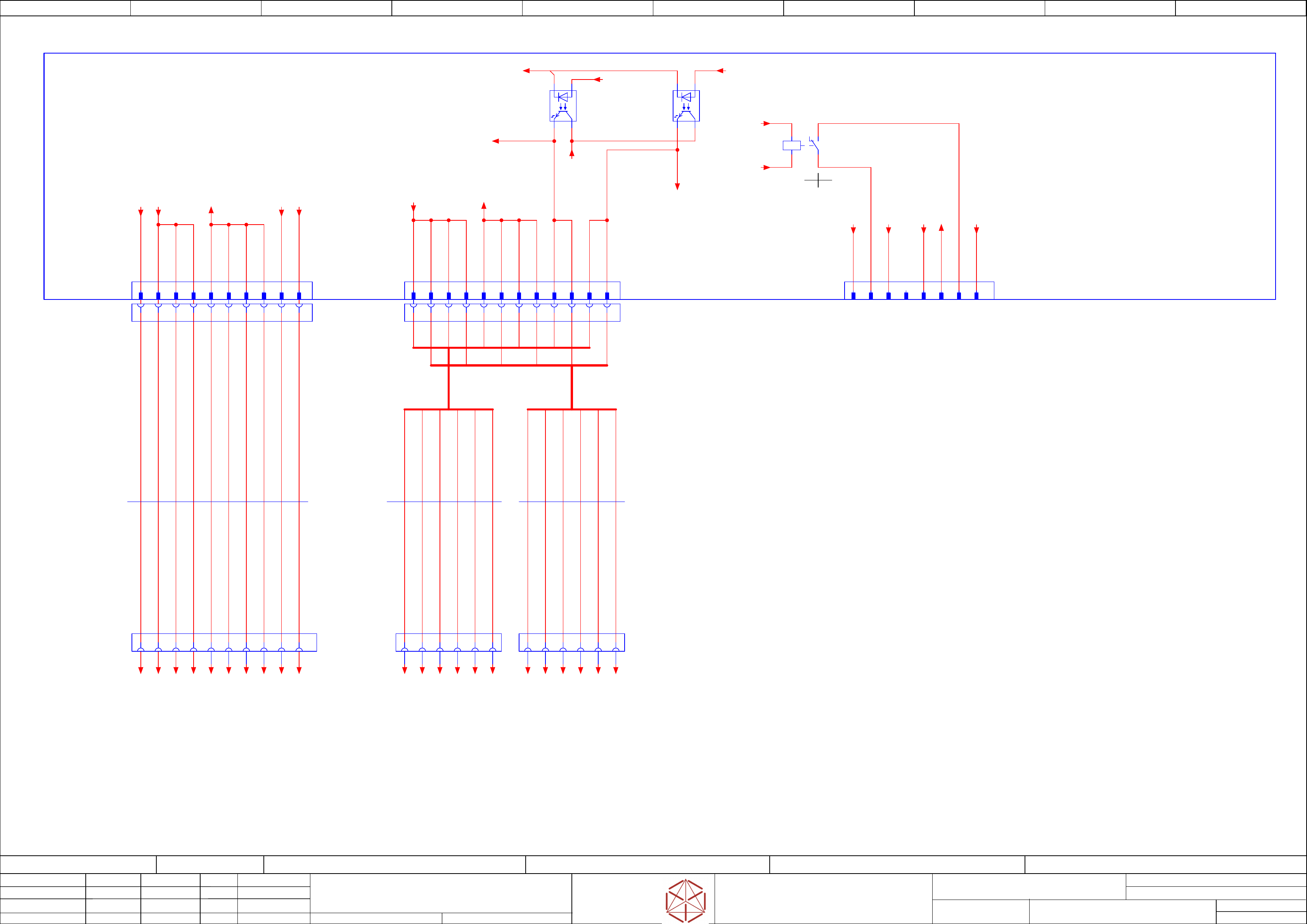
Low voltage supply-Distributor, MGCU,
Low voltage supply-Distributor, MGCU,
Low voltage supply-Distributor, MGCU,
Low voltage supply-Distributor, MGCU,
Shuttle, TCU
Shut
tle, TCU
Shuttle, TCU
Shuttle, TCU
Replaced by
Weitergabe sowie Vervielfältigung dieser Unterlage, Verwertung und
Mitteilung des Inhalts nicht gestattet, soweit nicht ausdrücklich zugestanden.
Proprietary Data, company confidential.
All rights reserved
Copying of this document, giving it to others and the use or
communication of the contents thereof, are forbidden without express authority.
Doc. No.
0 1 2 3 4 5 6 7 8 9
Privileged business information.
Do not release
Offenders are liable to payment of damages. All rights are reserved in the
event of the grant or the registration of a utility model or design.
Zuwiederhandlungen verpflichten zu Schadenersatz. Alle Rechte vorbehalten,
insbesondere für den Fall der Patenterteilung oder GM-Eintragung vorbehalten.
Page:
Function: Main Electrics
==ME=TX+03146155/46
drawing number:
03146155-010701LE3
Power Modules
P
ower Modules
Power Modules
Power Modules
GmbH & Co KG
ASM
Assembly Systems
Copyright reserved
Ed.
Original
Pingist
Date
Date
Modification
Appr
07.02.2018
Name
Size DIN A2
Sheet
46
/
5
-K1
-K1
-K1
-K1
A1
A2
/46.6 /46.6
NCNO
12
11
14
Note: FELV is for 'Functional Safe Voltage'
Note: FELV is for 'Functional Safe Voltage'
Note: FELV is for 'Functional Safe Voltage'
Note: FELV is for 'Functional Safe Voltage'
A1
A6
A1 A5
A3 A4 A5
A2 A3 A4 B1 B5B2 B3 B4 B6
B1 B6B2 B3 B4 B5
A2
A6
1 2 3 4 5 6 1 2 3 4 5 6
-X10
-
X10
-X10
-X10
Distributor Power DC 24 V
D-3000 1-178318-2
7
GND24
8
GND24
FG
10
24V(F5)
1
24V(F3)
2
24V(F4)
3
24V(F4)
4
24V(F4)
5
GND24
6
GND24
Distributor
Power DC 24 V
-X21.DI
-
X21.DI
-X21.DI
-X21.DI
2 41 3 6 85 7 109
-X10.FD
-X10.FD
-X10.FD
-X10.FD
1 2 3 4 5 6 7 8 9 10
10xAWG20
Single-wire
03148739
03148739
03148739
03148739
-W27
-
W27
-W27
-W27
BN 20 AWG
WH 20 AWG
GNYE 20 AWG
-X13
-X13
-X13
-X13
FELV_circuit
MGCU1&2 supply
D-3000 178326-2
B3
GND_FELV
B5
-PWR_ENA_FELV
B6
-PWR_FAIL_FELV
A3
GND_FELV
A4
GND_FELV
A5
-PWR_ENA_FELV
A6
-PWR_FAIL_FELV
B4
GND_FELV
-FD.A1
-FD
.A1
-FD.A1
-FD.A1
Fuse- and Distribution
Fuse- and Distribution
Fuse- and Distribution
Fuse- and Distribution
03136970
BN 20 AWG
BN 20 AWG
BN 20 AWG
BN 20 AWG
WH 20 AWG
WH 20 AWG
WH 20 AWG
-X17
-X17
-X17
-X17
Option
D-3000 1903601-2
B1
K1:11
B2 B3
GND24
A1
D24V(F3)
A2
24V_S_CO
A3
PWR_ENA
A4
K1:14
B4
PE
-K2
-K2
-K2
-K2
POWER_OK
+
- +
-K3
-K3
-K3
-K3
POWER_ENABLE
+
- +
-X13.FD
-
X13.FD
-X13.FD
-X13.FD
A1
A2
A3
A4
A5
A6
B1
B2
B3
B4
B5
B6
FELV_circuit
MGCU1
24V_Power & Signals
-X1p.MGCU1
-
X1p.MGCU1
-X1p.MGCU1
-X1p.MGCU1
FELV_circuit
MGCU2
24V_Power & Signals
-X1p.MGCU2
-
X1p.MGCU2
-X1p.MGCU2
-X1p.MGCU2
6xAWG20
Single core
03150043
03150043
03150043
03150043
-W21.1
-
W21.1
-W21.1
-W21.1
6xAWG20
Single core
03150043
03150043
03150043
03150043
-W21.2
-
W21.2
-W21.2
-W21.2
1 2 3 4 5 6 1 2 3 4 5 6
BN 20 AWG
WH 20 AWG
YE 20 AWG
WH 20 AWG
YE 20 AWG
WH 20 AWG
YE 20 AWG
WH 20 AWG
YE 20 AWG
BN 20 AWG
BN 20 AWG
BN 20 AWG
B1
24V_MGCU
B2
24V_MGCU
A1
24V_MGCU
A2
24V_MGCU
-24V(F3)
/45.2
-24V(F4)
/45.2
-GND24
/45.4
-GND_FELV
/45.0
-24V(F5)
/45.3
-PE
/45.4
-GND.6
+03147585/47.6
-GND.5
+03147585/47.6
-24V(F3).1
+03147585/47.5
-FG.1
+03147585/47.6
-GND.7
+03147585/47.6
-24V(F4).2
+03147585/47.5
-24V(F4).3
+03147585/47.6
-24V(F4).4
+03147585/47.6
-GND.8
+03147585/47.6
-24V(F5)
/45.3
-24V_MGCU
/45.1
-24V(F3)
/45.2
-PE
/45.4
-GND24
/45.4
-24V_S
/46.5
-PWR_ENA
/45.8
-24V_S
/46.6
-GND24
/45.4
-GND24
/45.4
-PWR_ENA
45.8
-24V_MGCU
/45.1
-PWR_ENA.FELV
to -X11/-X12 Trailing 1&2
-FD.A1-X11:B4 ==CH+03147980/53.2
-PWR_OK.FELV
to -X11/-X12 Trailing 1&2
==CH+03147980/53.2
-PWR_OK
45.2
-GND_FELV.3
==CH+GA/63.0
-GND_FELV.4
==CH+GA/63.1
-PWR_OK
==CH+GA/63.1
-PWR_ENA
==CH+GA/63.1
-GND_FELV.1
==CH+GA/61.0
-GND_FELV.2
==CH+GA/61.1
-PWR_OK
==CH+GA/61.1
-PWR_ENA
==CH+GA/61.1
-24V_MGCU.1
==CH+GA/61.0
-24V_MGCU.2
==CH+GA/61.0
-24V_MGCU.1
==CH+GA/63.0
-24V_MGCU.2
==CH+GA/63.0