00198460-01_DC_SIPLACE_TX-EditionV2_DE+EN.pdf - 第52页
electric_schematic SIPLACE TX_V2 electric_schematic SIPLACE TX_V2 electric_schematic SIPLACE TX_V2 electric_schematic SIPLACE TX_V2 90012669-010501LE3 Replaced by Distributor Main Connection & CAN Distributor Main Co…
electric_schematic SIPLACE TX_V2
electric_schematic SIPLACE TX_V2
electric_schematic SIPLACE TX_V2
electric_schematic SIPLACE TX_V2
90012669-010501LE3
Replaced by
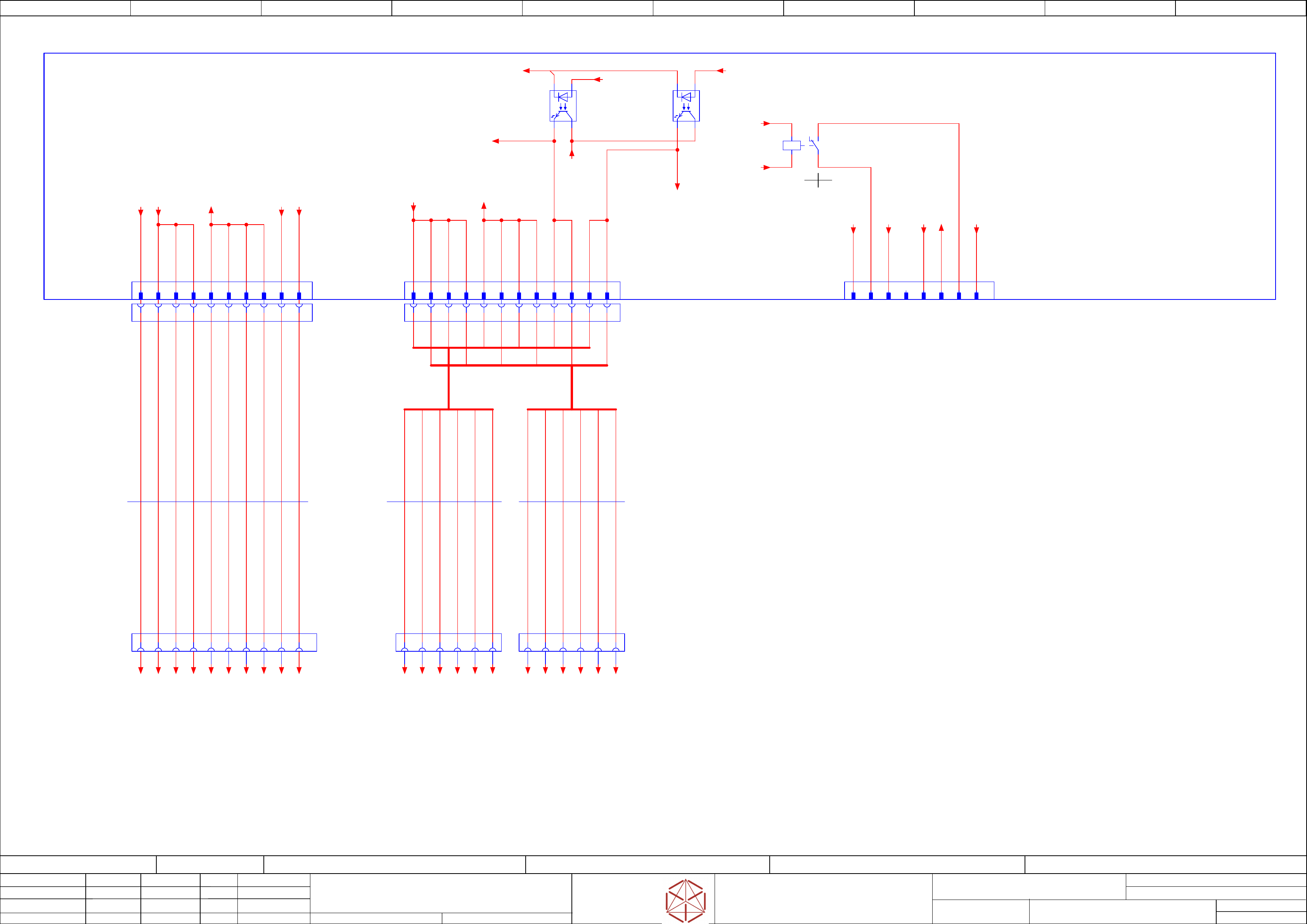
Low voltage supply-Distributor, MGCU,
Low voltage supply-Distributor, MGCU,
Low voltage supply-Distributor, MGCU,
Low voltage supply-Distributor, MGCU,
Shuttle, TCU
Shut
tle, TCU
Shuttle, TCU
Shuttle, TCU
Replaced by
Weitergabe sowie Vervielfältigung dieser Unterlage, Verwertung und
Mitteilung des Inhalts nicht gestattet, soweit nicht ausdrücklich zugestanden.
Proprietary Data, company confidential.
All rights reserved
Copying of this document, giving it to others and the use or
communication of the contents thereof, are forbidden without express authority.
Doc. No.
0 1 2 3 4 5 6 7 8 9
Privileged business information.
Do not release
Offenders are liable to payment of damages. All rights are reserved in the
event of the grant or the registration of a utility model or design.
Zuwiederhandlungen verpflichten zu Schadenersatz. Alle Rechte vorbehalten,
insbesondere für den Fall der Patenterteilung oder GM-Eintragung vorbehalten.
Page:
Function: Main Electrics
==ME=TX+03146155/46
drawing number:
03146155-010701LE3
Power Modules
P
ower Modules
Power Modules
Power Modules
GmbH & Co KG
ASM
Assembly Systems
Copyright reserved
Ed.
Original
Pingist
Date
Date
Modification
Appr
07.02.2018
Name
Size DIN A2
Sheet
46
/
5
-K1
-K1
-K1
-K1
A1
A2
/46.6 /46.6
NCNO
12
11
14
Note: FELV is for 'Functional Safe Voltage'
Note: FELV is for 'Functional Safe Voltage'
Note: FELV is for 'Functional Safe Voltage'
Note: FELV is for 'Functional Safe Voltage'
A1
A6
A1 A5
A3 A4 A5
A2 A3 A4 B1 B5B2 B3 B4 B6
B1 B6B2 B3 B4 B5
A2
A6
1 2 3 4 5 6 1 2 3 4 5 6
-X10
-
X10
-X10
-X10
Distributor Power DC 24 V
D-3000 1-178318-2
7
GND24
8
GND24
FG
10
24V(F5)
1
24V(F3)
2
24V(F4)
3
24V(F4)
4
24V(F4)
5
GND24
6
GND24
Distributor
Power DC 24 V
-X21.DI
-
X21.DI
-X21.DI
-X21.DI
2 41 3 6 85 7 109
-X10.FD
-X10.FD
-X10.FD
-X10.FD
1 2 3 4 5 6 7 8 9 10
10xAWG20
Single-wire
03148739
03148739
03148739
03148739
-W27
-
W27
-W27
-W27
BN 20 AWG
WH 20 AWG
GNYE 20 AWG
-X13
-X13
-X13
-X13
FELV_circuit
MGCU1&2 supply
D-3000 178326-2
B3
GND_FELV
B5
-PWR_ENA_FELV
B6
-PWR_FAIL_FELV
A3
GND_FELV
A4
GND_FELV
A5
-PWR_ENA_FELV
A6
-PWR_FAIL_FELV
B4
GND_FELV
-FD.A1
-FD
.A1
-FD.A1
-FD.A1
Fuse- and Distribution
Fuse- and Distribution
Fuse- and Distribution
Fuse- and Distribution
03136970
BN 20 AWG
BN 20 AWG
BN 20 AWG
BN 20 AWG
WH 20 AWG
WH 20 AWG
WH 20 AWG
-X17
-X17
-X17
-X17
Option
D-3000 1903601-2
B1
K1:11
B2 B3
GND24
A1
D24V(F3)
A2
24V_S_CO
A3
PWR_ENA
A4
K1:14
B4
PE
-K2
-K2
-K2
-K2
POWER_OK
+
- +
-K3
-K3
-K3
-K3
POWER_ENABLE
+
- +
-X13.FD
-
X13.FD
-X13.FD
-X13.FD
A1
A2
A3
A4
A5
A6
B1
B2
B3
B4
B5
B6
FELV_circuit
MGCU1
24V_Power & Signals
-X1p.MGCU1
-
X1p.MGCU1
-X1p.MGCU1
-X1p.MGCU1
FELV_circuit
MGCU2
24V_Power & Signals
-X1p.MGCU2
-
X1p.MGCU2
-X1p.MGCU2
-X1p.MGCU2
6xAWG20
Single core
03150043
03150043
03150043
03150043
-W21.1
-
W21.1
-W21.1
-W21.1
6xAWG20
Single core
03150043
03150043
03150043
03150043
-W21.2
-
W21.2
-W21.2
-W21.2
1 2 3 4 5 6 1 2 3 4 5 6
BN 20 AWG
WH 20 AWG
YE 20 AWG
WH 20 AWG
YE 20 AWG
WH 20 AWG
YE 20 AWG
WH 20 AWG
YE 20 AWG
BN 20 AWG
BN 20 AWG
BN 20 AWG
B1
24V_MGCU
B2
24V_MGCU
A1
24V_MGCU
A2
24V_MGCU
-24V(F3)
/45.2
-24V(F4)
/45.2
-GND24
/45.4
-GND_FELV
/45.0
-24V(F5)
/45.3
-PE
/45.4
-GND.6
+03147585/47.6
-GND.5
+03147585/47.6
-24V(F3).1
+03147585/47.5
-FG.1
+03147585/47.6
-GND.7
+03147585/47.6
-24V(F4).2
+03147585/47.5
-24V(F4).3
+03147585/47.6
-24V(F4).4
+03147585/47.6
-GND.8
+03147585/47.6
-24V(F5)
/45.3
-24V_MGCU
/45.1
-24V(F3)
/45.2
-PE
/45.4
-GND24
/45.4
-24V_S
/46.5
-PWR_ENA
/45.8
-24V_S
/46.6
-GND24
/45.4
-GND24
/45.4
-PWR_ENA
45.8
-24V_MGCU
/45.1
-PWR_ENA.FELV
to -X11/-X12 Trailing 1&2
-FD.A1-X11:B4 ==CH+03147980/53.2
-PWR_OK.FELV
to -X11/-X12 Trailing 1&2
==CH+03147980/53.2
-PWR_OK
45.2
-GND_FELV.3
==CH+GA/63.0
-GND_FELV.4
==CH+GA/63.1
-PWR_OK
==CH+GA/63.1
-PWR_ENA
==CH+GA/63.1
-GND_FELV.1
==CH+GA/61.0
-GND_FELV.2
==CH+GA/61.1
-PWR_OK
==CH+GA/61.1
-PWR_ENA
==CH+GA/61.1
-24V_MGCU.1
==CH+GA/61.0
-24V_MGCU.2
==CH+GA/61.0
-24V_MGCU.1
==CH+GA/63.0
-24V_MGCU.2
==CH+GA/63.0
electric_schematic SIPLACE TX_V2
electric_schematic SIPLACE TX_V2
electric_schematic SIPLACE TX_V2
electric_schematic SIPLACE TX_V2
90012669-010501LE3
Replaced by
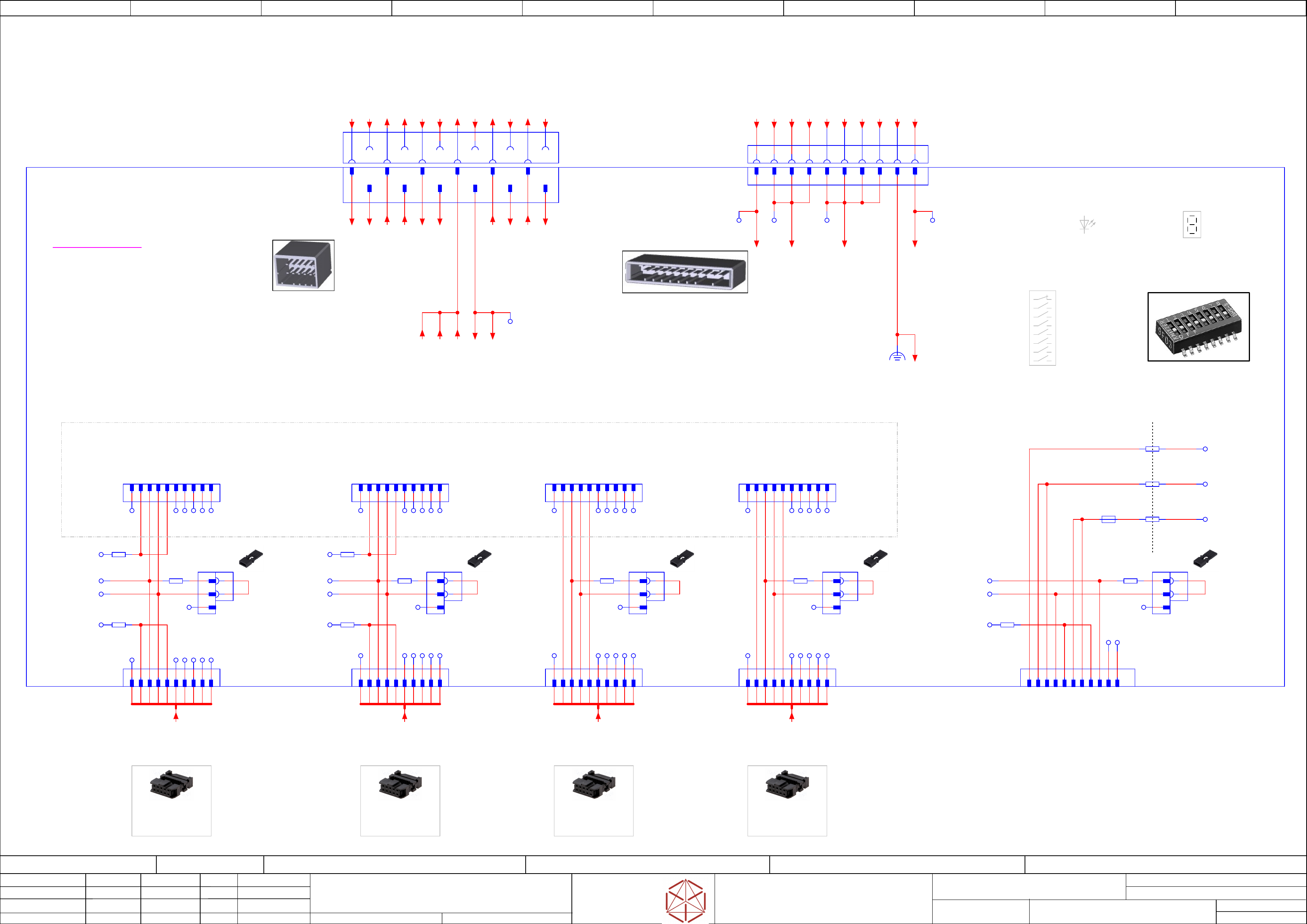
Distributor Main Connection & CAN
Distributor Main Connection & CAN
Distributor Main Connection & CAN
Distributor Main Connection & CAN
Replaced by
Weitergabe sowie Vervielfältigung dieser Unterlage, Verwertung und
Mitteilung des Inhalts nicht gestattet, soweit nicht ausdrücklich zugestanden.
Proprietary Data, company confidential.
All rights reserved
Copying of this document, giving it to others and the use or
communication of the contents thereof, are forbidden without express authority.
Doc. No.
00 01 02 03 04 05 06 07 08 09
Privileged business information.
Do not release
Offenders are liable to payment of damages. All rights are reserved in the
event of the grant or the registration of a utility model or design.
Zuwiederhandlungen verpflichten zu Schadenersatz. Alle Rechte vorbehalten,
insbesondere für den Fall der Patenterteilung oder GM-Eintragung vorbehalten.
Page:
Function: Main Electrics
==ME=TX+03147585/47
drawing number:
03156683-010101LE3
Distributor_Berlin
Distributor_B
erlin
Distributor_Berlin
Distributor_Berlin
GmbH & Co KG
ASM
Assembly Systems
Copyright reserved
Ed.
Original
Pingist
Date
Date
Modification
Appr
07.02.2018
Name
Size DIN A2
Sheet
47
/
3
(extern Service)
MC-identifcation
reserved
reserved
reserved
reserved
Serial-bootstrap
CAN-bootstrap
Reset-state
Option Switches
Dip-Switch SW1
LED-DISPLAY
LED-DISPL
AY
LED-DISPLAY
LED-DISPLAY
- GREEN -
- GREEN -
- GREEN -
- GREEN -
-LED1
-LED1
-LED1
-LED1
Display
Reset-LED
R
eset-LED
Reset-LED
Reset-LED
- RED -
- RED -
- RED -
- RED -
-D66
-D66
-D66
-D66
Reset
1 3 4 5 7 8 9 106
CAN Service-Interface
CAN Service-Interface
CAN Service-Interface
CAN Service-Interface
2
ON
ON
ON
ON
-CAN1.DI
-CAN1.DI
-CAN1.DI
-CAN1.DI
Machine_CAN-Bus 1
Machine_CAN-B
us 1
Machine_CAN-Bus 1
Machine_CAN-Bus 1
IDC-Female
Connector 10 pol.
1 3 4 5 7 8 9 1062
ON
ON
ON
ON
-CAN2.DI
-CAN2.DI
-CAN2.DI
-CAN2.DI
Machine_CAN-Bus 2
Machine_CAN-B
us 2
Machine_CAN-Bus 2
Machine_CAN-Bus 2
IDC-Female
Connector 10 pol.
1 3 4 5 7 8 9 1062
ON
ON
ON
ON
-CAN3.DI
-CAN3.DI
-CAN3.DI
-CAN3.DI
Conveyor_CAN-Bus 3
Con
veyor_CAN-Bus 3
Conveyor_CAN-Bus 3
Conveyor_CAN-Bus 3
IDC-Female
Connector 10 pol.
ON
ON
ON
ON ON
ON
ON
ON
Note:
Note:
Note:
Note:
The Solder bridges R27,
The S
older bridges R27,
The Solder bridges R27,
The Solder bridges R27,
R29 and R31 are open
R29 and R31 ar
e open
R29 and R31 are open
R29 and R31 are open
Note:
CAN5 and Special funktions
(ONE WIRE, +24VO)
- Currently Not Used -
03147585-020301le3
1 3 4 5 7 8 9 1062
-CAN4.DI
-CAN4
.DI
-CAN4.DI
-CAN4.DI
Conveyor_CAN-Bus 4
Con
veyor_CAN-Bus 4
Conveyor_CAN-Bus 4
Conveyor_CAN-Bus 4
IDC-Female
Connector 10 pol.
-DI
-DI
-DI
-DI
Distributor-Assembly
Distributor
-Assembly
Distributor-Assembly
Distributor-Assembly
I/O - Control Unit
I/O - Contr
ol Unit
I/O - Control Unit
I/O - Control Unit
-X22
-
X22
-X22
-X22
Safety-Loop & Signals
Safety-Loop & Signals
Safety-Loop & Signals
Safety-Loop & Signals
from Power supply SMPS
Dynamic-2100D Board-Mounting X-Key
1318126-1
A1
B1
A2
B2
A3 A4
B3 B4
A5 A6
B5 B6
-X21
-
X21
-X21
-X21
Power 24V DC
Power 24V DC
Power 24V DC
Power 24V DC
from Fuse and distribution board
1 2 3 4 5 6 7 8 9 10
MP11MP10
Distributor
Power DC 24 V
-X21.DI
-
X21.DI
-X21.DI
-X21.DI
-to Fuse and Distribution -
2 41 3 6 85 7 109
MP12MP9
Safety-loop
& Signals
-X22.DI
-
X22.DI
-X22.DI
-X22.DI
to Safety Breaker CSB
B1 B2
A1 A2 A3
B3
A4
B4
A5
B5
A6
B6
2
3
4
5
6
7
8
-SW1
-
SW1
-SW1
-SW1
1
-X1
-
X1
-X1
-X1
CAN1
CAN1
CAN1
CAN1
-X1_1
-
X1_1
-X1_1
-X1_1
CAN1
CAN1
CAN1
CAN1
Service-Interface
S
ervice-Interface
Service-Interface
Service-Interface
Location_1
Location_1
Location_1
Location_1
3
CAN_L
4
CAN_H
1 53
CAN_L
4
CAN_H
2 87 96
MP13
10
NC
-R369
0 Ohm
GND_C1
-R320
0 Ohm
GND_C1
NC
NC
NC
NC
NC
NC
1
-X6
-
X6
-X6
-X6
CAN-Bus Termination
CAN-B
us Termination
CAN-Bus Termination
CAN-Bus Termination
CAN1 Location_1
CAN1 Location_1
CAN1 Location_1
CAN1 Location_1
2
3
1
-J6
-
J6
-J6
-J6
Jumper
Jumper
Jumper
Jumper
2
NC
-R33
120 Ohm
CAN_L
CAN_H
1 2 5 6 7 8 9 10
NC
NC
NC
NC
NC
-X2
-
X2
-X2
-X2
CAN2
CAN2
CAN2
CAN2
1 53
CAN_L
4
CAN_H
2 87 96 10
NC
-R367
0 Ohm
GND_C2
-R322
0 Ohm
GND_C2
NC
NC
NC
NC
NC
1
-X7
-
X7
-X7
-X7
CAN-Bus Termination
CAN-B
us Termination
CAN-Bus Termination
CAN-Bus Termination
CAN1 Location_2
CAN1 Location_2
CAN1 Location_2
CAN1 Location_2
2
3
1
-J7
-
J7
-J7
-J7
Jumper
Jumper
Jumper
Jumper
2
NC
-R124
120 Ohm
/47.08
CAN_L
CAN_H
-X2_1
-
X2_1
-X2_1
-X2_1
CAN2
CAN2
CAN2
CAN2
Service-Interface
S
ervice-Interface
Service-Interface
Service-Interface
Location_2
Location_2
Location_2
Location_2
3
CAN_L
4
CAN_H
NC
1 2 5 6 7 8 9 10
NC
NC
NC
NC
NC
-X3
-
X3
-X3
-X3
CAN3
CAN3
CAN3
CAN3
1 53
CAN_L
4
CAN_H
2 87 96 10
NC
NC
NC
NC
NC
NC
1
-X8
-
X8
-X8
-X8
CAN-Bus Termination
CAN-B
us Termination
CAN-Bus Termination
CAN-Bus Termination
CAN3 _ Conveyor
CAN3 _ Con
veyor
CAN3 _ Conveyor
CAN3 _ Conveyor
2
3
1
-J8
-
J8
-J8
-J8
Jumper
Jumper
Jumper
Jumper
2
NC
-R125
120 Ohm
-X3_1
-
X3_1
-X3_1
-X3_1
CAN3
CAN3
CAN3
CAN3
Service-Interface
S
ervice-Interface
Service-Interface
Service-Interface
Conveyor
Conveyor
Conveyor
Conveyor
3
CAN_L
4
CAN_H
NC
1 2 5 6 7 8 9 10
NC
NC
NC
NC
NC
-X4
-
X4
-X4
-X4
CAN4
CAN4
CAN4
CAN4
1 53
CAN_L
4
CAN_H
2 87 96 10
NC
NC
NC
NC
NC
NC
1
-X9
-
X9
-X9
-X9
CAN-Bus Termination
CAN-B
us Termination
CAN-Bus Termination
CAN-Bus Termination
CAN4 _ Options
CAN4 _ Options
CAN4 _ Options
CAN4 _ Options
2
3
1
-J9
-
J9
-J9
-J9
Jumper
Jumper
Jumper
Jumper
2
NC
-R126
120 Ohm
-X4_1
-
X4_1
-X4_1
-X4_1
CAN4
CAN4
CAN4
CAN4
Service-Interface
S
ervice-Interface
Service-Interface
Service-Interface
Options
Options
Options
Options
3
CAN_L
4
CAN_H
NC
1 2 5 6 7 8 9 10
NC
NC
NC
NC
NC
-X13
-
X13
-X13
-X13
CAN_5 and
CAN_5 and
CAN_5 and
CAN_5 and
Special Funktions
Special Funktions
Special Funktions
Special Funktions
1 5 9
CAN_L
4
CAN_H
2 876 10
-R324
0 Ohm
GND_C4
NC
1
-X5
-
X5
-X5
-X5
CAN-Bus Termination
CAN-Bus Termination
CAN-Bus Termination
CAN-Bus Termination
CAN5 Special Funktions
CAN5 Special Funktions
CAN5 Special Funktions
CAN5 Special Funktions
2
3
1
-J5
-
J5
-J5
-J5
Jumper
Jumper
Jumper
Jumper
2
NC
-R124
120 Ohm
/47.03
CAN_L
CAN_H
11
-R31
0 Ohm
(NOT USED)
(NO
T USED)
(NOT USED)
(NOT USED)
ONE WIRE
3
-R29
0 Ohm
(NOT USED)
(NO
T USED)
(NOT USED)
(NOT USED)
LGND
-R27
0 Ohm
(NOT USED)
(NO
T USED)
(NOT USED)
(NOT USED)
+24VO
-F3
3A
NC
12
Functional
Grounding
-IN
-Safety_Loop1.1
==CH+03148020/55.01
-OUT
-Safety_Loop1.9
==CH+03148020/56.09
-IN
-Safety_Loop2.1
==CH+03148020/55.01
-DI13_PWR_ENA
/49.02
-OUT
-Safety_Loop2.9
==CH+03148020/56.09
-DI0_Safety_Loop_OK
/49.00
-Safety_Loop1_ext.in
==CH+03148020/57.01
-Safety_Loop1_ext.out
==CH+03148020/57.01
-Safety_Loop2_ext.in
==CH+03148020/57.03
-Safety_Loop2_ext.out
==CH+03148020/57.03
(SSK)-Start_Button.1
==CH+03148020/55.01
(SSK)-Start_Button.3
==CH+03148020/55.07
(SSK)-Start_Button.2
==CH+03148020/55.04
-DI10_24V(F12)_S
49.01
-24V(F12)_S
48.01
48.06
==CH+03148020/55.09
==CH+03148020/57.00
==CH+03148020/57.02
==CH+03148020/57.05
==CH+03148020/58.01
==CH+03148020/59.07
-GND.6
+03146155/46.01
-GND.5
+03146155/46.01
-24V(F3).1
+03146155/46.01
-FG.1
+03146155/46.02
-GND.7
+03146155/46.01
-24V(F4).2
+03146155/46.01
-24V(F4).3
+03146155/46.01
-24V(F4).4
+03146155/46.01
-GND.8
+03146155/46.02
-24V(F5)
+03146155/45.03
-24V(F4)
48.03
48.05
48.06
48.06
48.08
==CH+03148020/55.01
==CH+03148020/55.02
==CH+03148020/55.05
==CH+03148020/55.05
==CH+03148020/56.01
==CH+03148020/56.02
==CH+03148020/56.04
==CH+03148020/56.05
==CH+03148020/56.08
==CH+03148020/56.08
==CH+03148020/57.01
==CH+03148020/57.01
==CH+03148020/57.03
==CH+03148020/57.04
==CH+03148020/57.05
==CH+03148020/58.01
==CH+03148020/58.01
==CH+03148020/58.08
==CH+03148020/59.01
==CH+03148020/59.05
==CH+03148020/59.06
==CH+03148020/59.06
-24V(F3)
==CH+03148020/55.08
==CH+03148020/58.08
-24V(F5)
==CH+03148020/57.07
-LGND
48.08
48.08
==CH+03148020/55.01
==CH+03148020/55.04
==CH+03148020/55.07
==CH+03148020/56.01
==CH+03148020/56.04
==CH+03148020/56.07
==CH+03148020/57.00
==CH+03148020/57.01
==CH+03148020/57.02
==CH+03148020/57.04
==CH+03148020/57.05
==CH+03148020/57.06
==CH+03148020/57.06
==CH+03148020/57.07
==CH+03148020/58.02
==CH+03148020/58.02
==CH+03148020/58.02
==CH+03148020/58.04
==CH+03148020/58.05
==CH+03148020/58.09
==CH+03148020/59.01
==CH+03148020/59.01
==CH+03148020/59.05
==CH+03148020/59.05
==CH+03148020/59.07
==CH+03148020/59.08
==CH+03148020/59.08
==CH+03148020/59.08
==CH+03148020/59.09
==CH+03148020/59.09
-24V(F12)_S.DI
+03146155/44.06
-S_Start_SSK
+03146155/44.06
-S_Loop1_OUT
+03146155/44.05
24V-PCC
-S_Loop2_OUT
+03146155/44.05
24V-PCC
-S_Loop1_IN
+03146155/44.05
End
-S_Loop2_IN
+03146155/44.05
End
-S_Loop1_ext.in
+03146155/44.07
-S_Loop1_ext.out
+03146155/44.07
-S_Loop2_ext.in
+03146155/44.07
-S_Loop2_ext.out
+03146155/44.07
-DI13_PWR_ENA
+03146155/44.06
-DI0_S_Loop_OK
+03146155/44.05
-CAN1_DI
==OV+CH/18.00
==OV+CH/19.00
-FG
/48.05
/48.06
==CH+03148020/57.08
==CH+03148020/58.09
-CAN2_DI
==OV+CH/18.01
==OV+CH/19.01
-CAN3_DI
==OV+CH/18.02
==OV+CH/19.02
-CAN4_DI
==OV+CH/18.03
==OV+CH/19.03
electric_schematic SIPLACE TX_V2
electric_schematic SIPLACE TX_V2
electric_schematic SIPLACE TX_V2
electric_schematic SIPLACE TX_V2
90012669-010501LE3
Replaced by
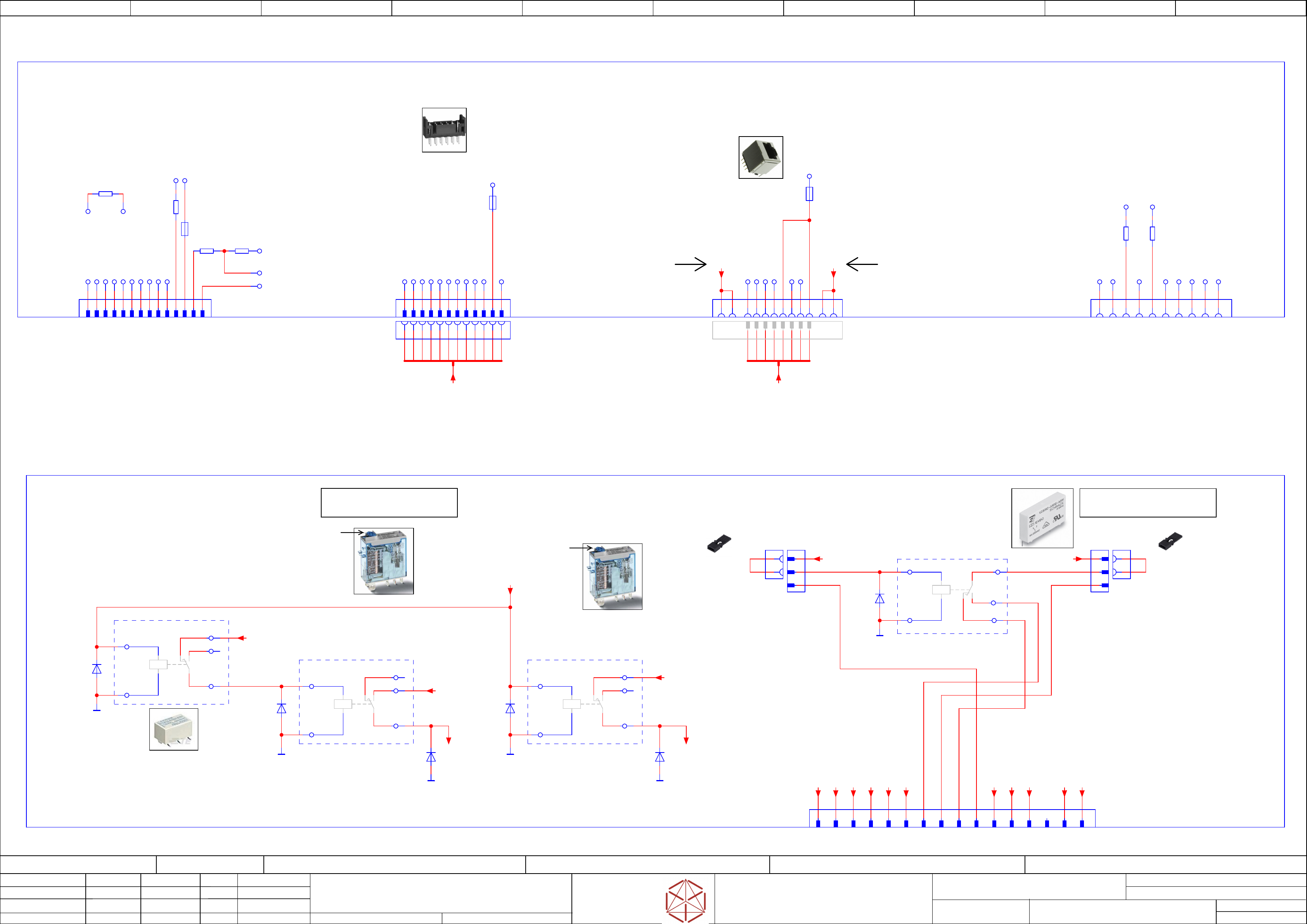
Distributor Control Connection & Relay
Distributor Control Connection & Relay
Distributor Control Connection & Relay
Distributor Control Connection & Relay
Replaced by
Weitergabe sowie Vervielfältigung dieser Unterlage, Verwertung und
Mitteilung des Inhalts nicht gestattet, soweit nicht ausdrücklich zugestanden.
Proprietary Data, company confidential.
All rights reserved
Copying of this document, giving it to others and the use or
communication of the contents thereof, are forbidden without express authority.
Doc. No.
00 01 02 03 04 05 06 07 08 09
Privileged business information.
Do not release
Offenders are liable to payment of damages. All rights are reserved in the
event of the grant or the registration of a utility model or design.
Zuwiederhandlungen verpflichten zu Schadenersatz. Alle Rechte vorbehalten,
insbesondere für den Fall der Patenterteilung oder GM-Eintragung vorbehalten.
Page:
Function: Main Electrics
==ME=TX+03147585/48
drawing number:
03156683-010101LE3
Distributor_Berlin
Distributor_B
erlin
Distributor_Berlin
Distributor_Berlin
GmbH & Co KG
ASM
Assembly Systems
Copyright reserved
Ed.
Original
Pingist
Date
Date
Modification
Appr
07.02.2018
Name
Size DIN A2
Sheet
48
/
3
1 2 3 4 6 7 85
LITTLEFUSE
33V 1,1A
SMT 1812
1 2 3 4 6 7 8 129 10 115
LITTLEFUSE
13,2V 0,75A
SMT 1812
LITTLEFUSE
13,2V 0,75A
SMT 1812
SHIELD SHIELD
Functional
Grounding
Functional
Grounding
ON
ON
ON
ONON
ON
ON
ON
Note:
The relay contact drawing shows the relay
in the non-active mode (normal position).
- not used -
- not used -
Note:
The relay contact drawing shows the relay
in the non-active mode (normal position).
Test button
Test button
- only for Service -
-X14
-X14
-X14
-X14
RS485
RS485
RS485
RS485
for PSU
f
or PSU
for PSU
for PSU
1 2 3 4 5 6 87
-X14.DI
-
X14.DI
-X14.DI
-X14.DI
RS485/PSU
RJ45
1 2 3 4 5 6 7 8
RS485_OUT_NINV
RS485_OUT_INV
RS485_IN_INV
RS485_IN_NINV
-LGND
-LGND
-F3
+24V0
-X11
-
X11
-X11
-X11
Diff. Communication to
Di
ff. Communication to
Diff. Communication to
Diff. Communication to
FUSE-Detection
FUSE-Detection
FUSE-Detection
FUSE-Detection
FUSE_IN_MISO_NINV
FUSE_IN_MISO_INV
FUSE_OUT_CLK_NINV
FUSE_OUT_CLK_INV
FUSE_OUT_LATCH_NINV
FUSE_OUT_LATCH_INV
MTSR
EXT1
EXT2
DETECT_DISTRBRD
-LGND
-F2
1 2 3 4 5 6 7 8 9 10 11 12
1 2 3 4 5 6 7 8 9 10 11 12
-X11.DI
-
X11.DI
-X11.DI
-X11.DI
Fuse-Diagnostic
serial interface
+5V0
-X10
-
X10
-X10
-X10
Analog + Program
Analog + Pr
ogram
Analog + Program
Analog + Program
1 2 3 4 5 6 7 8 9 10 11 12 13 14
AI_0
AI_1
AI_2
AI_3
AI_4
AI_5
AI_6
AI_7
-LGND
-AGND
TRST_N
+5V0
TXD0_0
-F4
-R297
120 Ohm
-R298
4k7
RXD0_0
-R378
10k
-LGND
9 13 10 14
-R34
0 Ohm
-LGND -AGND
-DI
-DI
-DI
-DI
Distributor-Assembly TX_V2
Distributor
-Assembly TX_V2
Distributor-Assembly TX_V2
Distributor-Assembly TX_V2
I/O - Control Unit
I/O - Contr
ol Unit
I/O - Control Unit
I/O - Control Unit
03147585
03147585
03147585
03147585
-X98
-
X98
-X98
-X98
Debug
Debug
Debug
Debug
1 2 3 4 5 6 87 109
-LGND
TDI
-R1
120 Ohm
-R158
120 Ohm
RSTIN_N
TRST_N
BRKOUT_N
TMS
+3V3
TDO
BRKIN_N
TCK
-X37
-X37
-X37
-X37
Reserve-I/O
R
eserve-I/O
Reserve-I/O
Reserve-I/O
K3_Connection
K3_Connection
K3_Connection
K3_Connection
Mini-Mate-N-Look 16pol(Dual Row)
1-794075-0
8
K3_11
1 2 6 129
K3_12
7
K3_14
1110
K3_A1+
3 4 5 13 1514 16
-DI
-DI
-DI
-DI
Distributor-Assembly TX_V2
Distributor
-Assembly TX_V2
Distributor-Assembly TX_V2
Distributor-Assembly TX_V2
I/O - Control Unit
I/O - Contr
ol Unit
I/O - Control Unit
I/O - Control Unit
03147585
03147585
03147585
03147585
1
2
3
1
-J1.K3
-
J1.K3
-J1.K3
-J1.K3
Jumper J1
Jumper J1
Jumper J1
Jumper J1
for -X40
f
or -X40
for -X40
for -X40
2
-X40
-X40
-X40
-X40
1
2
3
K3_A1+
1
-J2.K3
-J2.K3
-J2.K3
-J2.K3
Jumper J2
Jumper J2
Jumper J2
Jumper J2
for -X41
f
or -X41
for -X41
for -X41
2
-X41
-X41
-X41
-X41
A1+
A2-
14
11
K3_12
12
-K4
-K4
-K4
-K4
Slimline PCB Relay SNR
Rated current 6A, Coil: 24VDC
V23092A1024A201 (2-1393236-1)
03131716
D22
-LGND
5 (A1+)
1 (A2-)
4 (11)
2 (12)
3 (14)
-K3
-K3
-K3
-K3
Fan control (ON/OFF)
F
an control (ON/OFF)
Fan control (ON/OFF)
Fan control (ON/OFF)
Finder - Miniature industrial relays, 16 A
46 Series (46.61.9.024.0040)
03123859
-D99
-D57
-LGND
-LGND
5 (A1+)
1 (A2-)
4 (11)
2 (12)
3 (14)
-K2
-K2
-K2
-K2
Finder - Miniature industrial relays, 16 A
46 Series (46.61.9.024.0040)
03123859
-D136
-D137
-LGND
-LGND
3
8
5
1
10
-K1
-K1
-K1
-K1
Fan control (ON/OFF)
F
an control (ON/OFF)
Fan control (ON/OFF)
Fan control (ON/OFF)
Signal Relays
Rated current: 1A
Coil voltage: 24VDC
V23026-D1024-B201-125V (1393776-7)
03151288
-D100
-LGND
-RS485_PSU
RS485 Power supply units
+03146155/43.06
-W17.1
-RS485_DIAG_F&D
Fuse and distribution
Diagnostic serial interface
+03146155/45.07
-W17
-FG
-FG
-FG
-FG
-FG
-FG
-FG
-FG
-DO0_Res
/49.06
-DO8_Res
/49.07
-24V(F12)_S
/47.03
-DI23_Res
/49.03
-DI22_Res
/49.03
-DI21_Res
/49.03
-DO19_Res
/49.09
-24V(F4)
/47.06
-24V(F4)
/47.06
-LGND
/47.06
-LGND
/47.06
+-24V(F4)
/47.06
-DO8_Res
/49.07
-DO20_Fan_Contr
49.09
-24V(F4)
47.06
-24V(F4)
47.06
-24V(F12)_S
47.03
-24V(F4)_K2
OUT20(K2) / Safety(K1)
to Connector -X34
==CH+03148020/59.01
-24V(F4)_K3
OUT20(K3)
to Connector -X35
==CH+03148020/59.05