SIPLACE D2 规格说明书英文版.pdf - 第12页
12 Placement Heads Technical Data 12-nozzle Collect & Place hea d CO camera type 28 12-nozzle Collect & Place head CO camera type 29 12-nozzle Collect & Place head CO camera type 38 6-nozzle Collect & Pla…
11
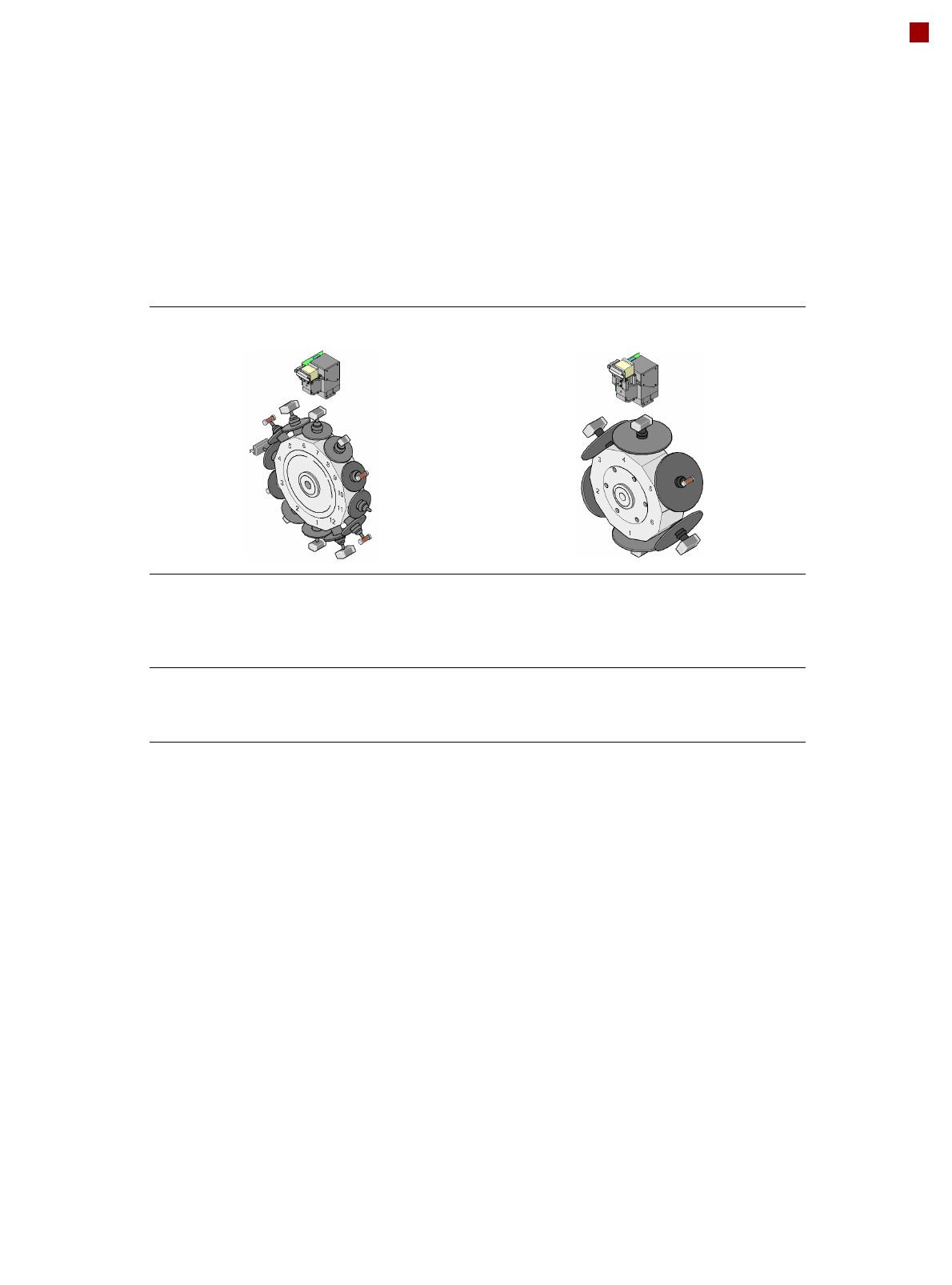
Placement Heads
Standard Functions / Options
12-nozzle Collect&Place head 6-nozzle Collect&Place head
Standard-
functions
Camera, vacuum sensor, force
measurement, PCB warpage,
check, individual recording for
each component
Standard
functions
High-resolution camera,
vacuum sensor, force measure-
ment, PCB warpage, check,
individual recording for each
component
Options High-resolution camera, compo-
nent sensor, short nozzle, short
sleeve, nozzle changers, special
nozzles
Options Short nozzle, short sleeve,
nozzle changers, special
nozzles
12
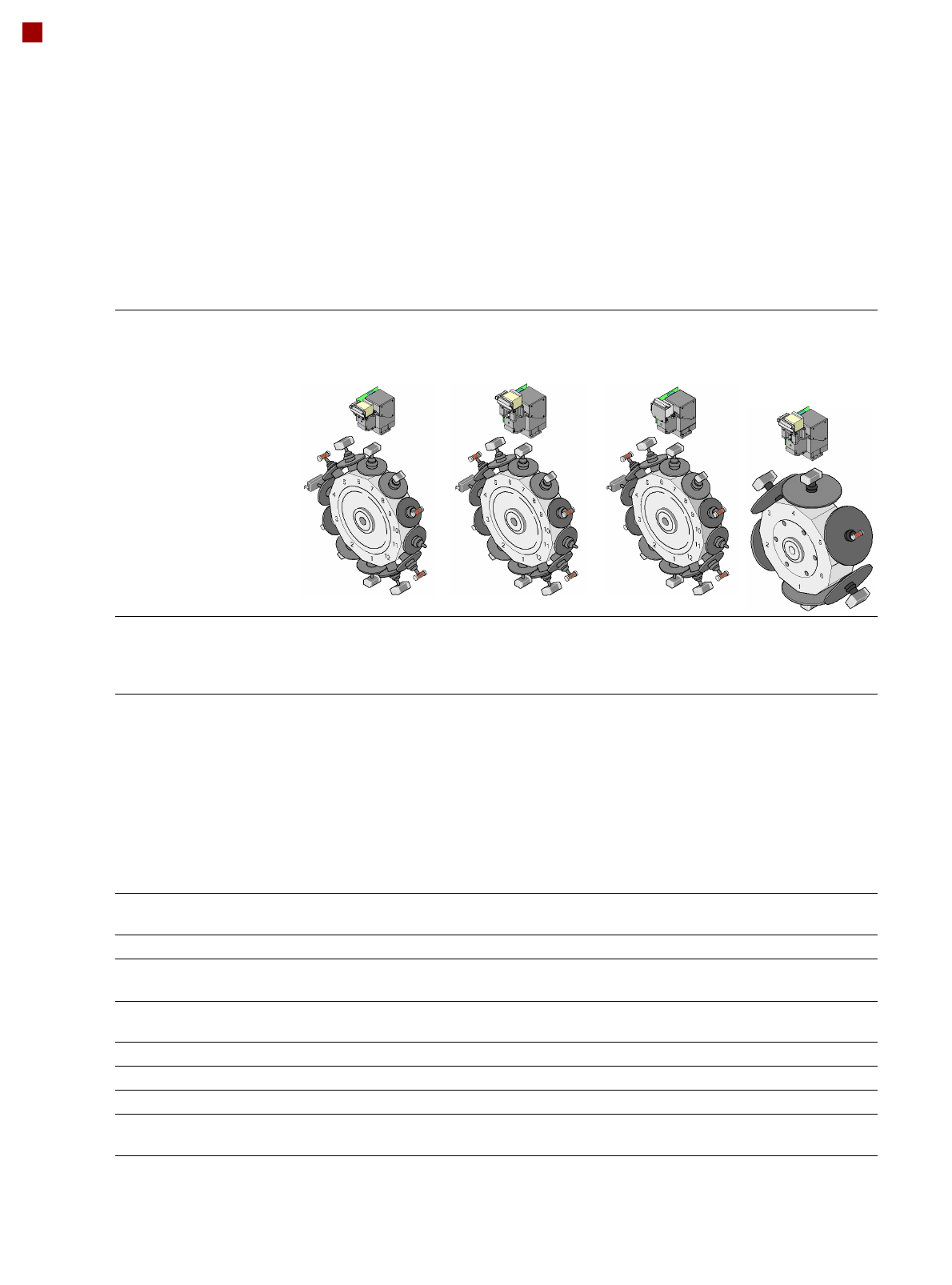
Placement Heads
Technical Data
12-nozzle
Collect&Place head
CO camera type 28
12-nozzle
Collect&Place head
CO camera type 29
12-nozzle
Collect&Place head
CO camera type 38
6-nozzle
Collect&Place
head
CO camera type 29
Component range
a
a) Please note that the range of components that can be placed is also affected by the pad geometry, customer-specific stan-
dards, component packaging tolerances and component tolerances
0402 to PLCC44,
BGA, µBGA, flip-
chip, TSOP, QFP, SO
to SO32, DRAM
0201
b
to flip-chip, bare
die, PLCC44, BGA,
µBGA, TSOP, QFP, SO
to SO32, DRAM
b) With 0201 package
01005
c
to 16 x
16 mm²
c) With 01005 package
0201to 27 x
27 mm²
Component specification
max. height
min. lead pitch
min. lead width
min. ball pitch
min. ball diameter
min. dimensions
max. dimensions
max. weight
6 mm
0.5 mm
0.2 mm
0.35 mm
0.2 mm
1.0 x 0.5 mm²
18.7 x 18.7 mm²
2 g
6 mm
0.3 mm
0.15 mm
0.25 mm
0.14 mm
0.6 x 0.3 mm²
b
18.7 x 18.7 mm²
2 g
6 mm
0.25 mm
0.1 mm
0.25 mm
0.14 mm
0.4 x 0.2 mm²
16 x 16 mm²
2 g
8.5 mm
0.3 mm
0.15 mm
0.25 mm
d
0.35 mm
e
0.14 mm
d
0.2 mm
e
0.6 x 0.3 mm²
27 x 27 mm²
5 g
d) For components < 18 x 18 mm²
e) For components 18 x 18 mm²
Programmable placement
force
2.4 N - 5.0 N 2.4 N - 5.0 N 2.4 N - 5.0 N 2.4 N - 5.0 N
Nozzle types 9xx 9xx 9xx 8xx, 9xx
X/Y accuracy
f
f) The accuracy value was measured using the vendor-neutral IPC standard
± 50 µm/3
± 67 µm/4
± 50 µm/3
± 67 µm/4
± 50 µm/3
± 67 µm/4
± 52.5 µm/3
± 70 µm/4
Angular accuracy ± 0.53°/3
± 0.71°/4
± 0.53°/3
± 0.71°/4
± 0.53°/3
± 0.71°/4
± 0.225°/3
± 0.3°/4
Component range 98% 98.5% 96% 99.5%
Component camera type 28 29 38 29
Illumination levels 5 5 5 5
Possible illumination level
settings
256
5
256
5
256
5
256
5
13
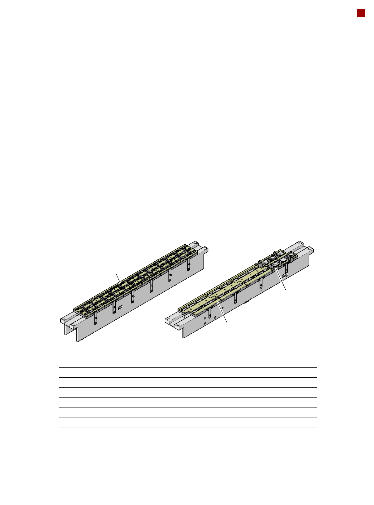
Placement Heads
Nozzle Changers
Magazine for 12
type 9xx nozzles
Nozzle changer for the
6-nozzle Collect&Place head (NCH6)
Magazine for 6
type 9xx nozzles
Magazine for 6
type 8xx nozzles
Description
Nozzle changers increase
the flexibility of placement
heads when processing dif-
ferent components. The noz-
zle configuration can be
quickly modified for new
placement jobs. Exactly
defined positions and the
perfect seating of the nozzle
in the garage guarantee min-
imal radial eccentricity at the
placement head.
Two nozzle changers can be
installed for the 6-nozzle or
12-nozzle Collect&Place
heads (C&P6 or C&P12):
Location 1: 1 nozzle changer
(NCH6 or NCH12)
Location 2: 1 nozzle changer
(NCH6 or NCH12)
Nozzle changer for the
12-nozzle Collect&Place head (NCH12)
Nozzle changer for the 12-nozzle Collect&Place head
Dimensions (length x width x height) 565 x 63 x 78 mm³
Number of magazines min. 1 / max. 6, each with 12 nozzle holders
Nozzle types 9xx
Compressed air connection 0.48 MPa (4.8 bar)
Nozzle changer for the 6-nozzle Collect&Place head
Dimensions (length x width x height) 565 x 69 x 87 mm³
Number of magazines min. 1 / max. 4, each with 6 nozzle holders
Nozzle types 8xx, 9xx
Compressed air connection 0.48 MPa (4.8 bar)