TK25947.Auto Create Parts Recognition Data.pdf - 第3页
SMT Software Engineering Group IM Operations Y AMAHA MOTOR CO., L TD MDOC-SOFT50408 3/8 as “0” according to the parts i mage. 4. Parts size (X, Y , ReflectLL, Lead Wi dth) may differ from the actual size bec…
SMT Software Engineering Group
IM Operations YAMAHA MOTOR CO., LTD
MDOC-SOFT50408
2/8
1. Model and Version
Supported models and version are as follows.
Table1 Model and Version
Model・Software Version Remarks
YS series mounter V3.46STD R1.000 or later
YSM40, YSM20 V4.50STD R1.000 or later
2. Introduction
This function can automatically create parts data and recognition data based on parts
images. It is possible to create accurate parts data in a short time regardless of operator’s
skill.
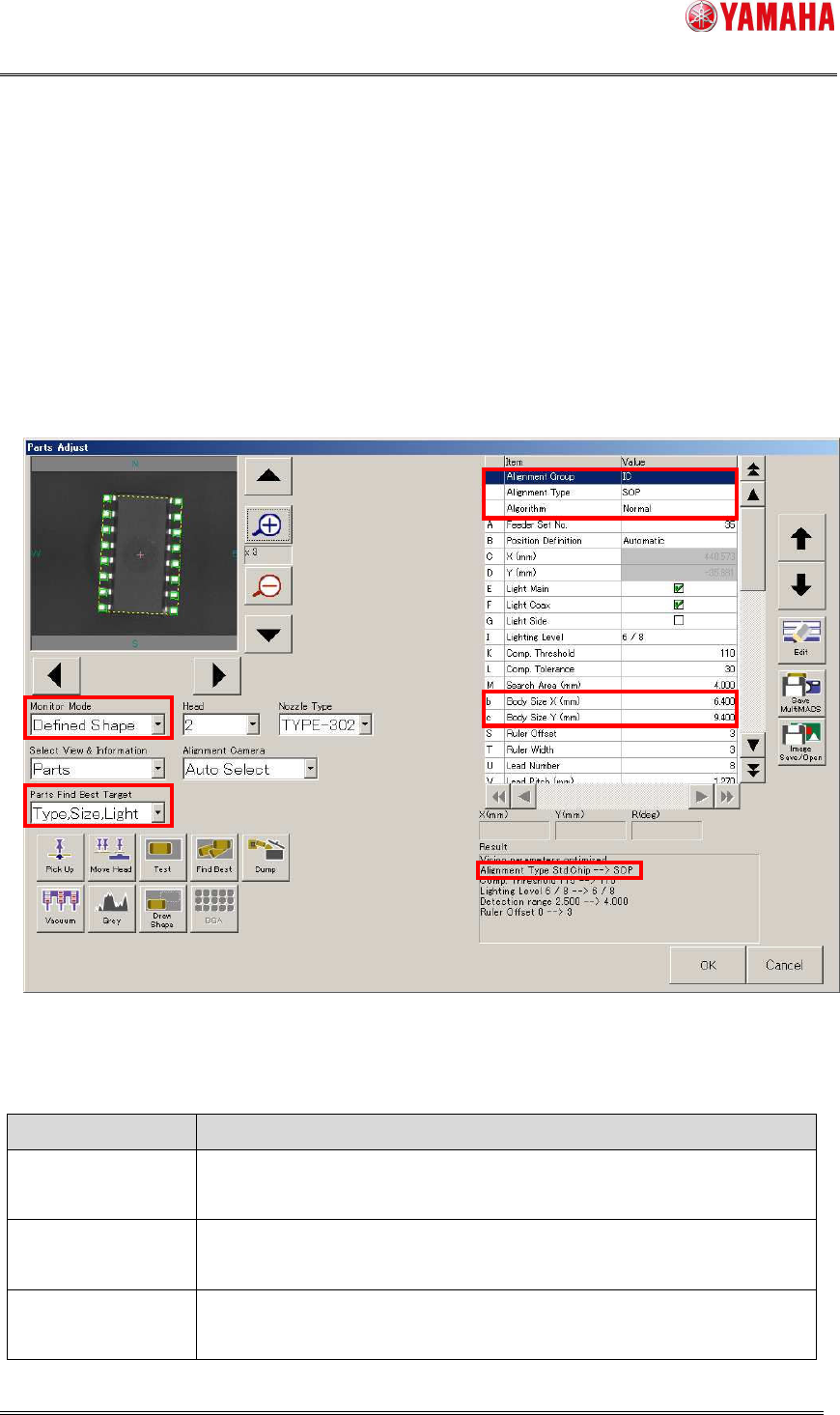
The [Parts Find Best Target] combo box has been added on the [Parts Adjust] screen.
When you select a target and click the [Find Best] button, each parameter of the selected
parts is automatically created.
Also, “Defined Shape” is added to the [Monitor Mode] combo box. In this mode, parts
recognition image and a defined shape are overlaid on the view window.
In addition, [Alignment Group], [Alignment Type], [Algorithm], [Body Size X], and [Body
Size Y] are displayed on the grids of parts data, which makes it easy for you to confirm
and edit the setting values.
< Remarks >
This function has the following limitations.
1. In any of the following conditions, [Alignment Type] and [Body Size] are NOT created
by the [Find Best] button.
When the [Find Best] button is pressed on the [Parts Adjust] screen that opens at
pick up error or recognition error during auto-running.
When the [Find Best] button is pressed on the [Random Ball Edit] screen or the
[Pin Position Edit screen] screen.
When parts recognized by a single camera is selected and the [Find Best] button
is pressed.
2. Parts data of random ball parts is NOT automatically created.
3. Recognition data of [Datum Angle] set to “Normal” is created assuming [defined angle]
SMT Software Engineering Group
IM Operations YAMAHA MOTOR CO., LTD
MDOC-SOFT50408
3/8
as “0” according to the parts image.
4. Parts size (X, Y, ReflectLL, Lead Width) may differ from the actual size because it is
measured based on the electrode position and lighting condition.
5. When large parts need divided recognition, parts data is NOT automatically created.
6. If auto creation is executed while no parts are picked on head, there is a possibility that
data to recognize nozzle shape may be created.
7. On a machine equipped with both scan camera and multi-camera, recognition is
always performed by multi-camera.
Fig.1 Parts Adjust screen
Table2 “Parts Find Best Target” combo box
Item name Operation at Parts Find Best
Light Parameters of Lighting Level and Comp. Threshold are
automatically adjusted.
Size, Light Body Size is automatically created without any change of
“Alignment Type”. Also, “Find Best” of the light level is executed.
Type, Size, Light “Alignment Type” and “Body Size” are automatically created.
Also, Find Best of the light level is executed.

SMT Software Engineering Group
IM Operations YAMAHA MOTOR CO., LTD
MDOC-SOFT50408
4/8
* For details of parameters automatically created, refer to Table 3.
* The [Parts Find Best Target] combo box is managed by operator’s level.
([Parts] - [Adjust Find Best Target] in the operator level edit screen)
3. Procedure of parts recognition data auto creation
3.1 Auto creation of alignment type and measurement data
If you don’t know which alignment type to select, execute auto creation of alignment type
and measurement data through the following procedure.
(1) Parts basic data
On the [Parts] screen, select parts data and enter the following information.
[Basic] tab ・・・ [Required Nozzle], [Package], [Feeder Type] etc.
[Pick] tab ・・・ [Feeder Set No.] etc.
[Shape] tab ・・・ [Body Size X], [Body Size Y], [Body Size Z]
* [Body Size X] and [Body Size Y] are used to roughly decide the camera area, so that
they don’t need to be exact values.
* The first image is applied with Light Main=ON, Light Coax=ON, and Lighting Level=7/8.
Therefore, you don’t need to make lighting settings for that.
(2) Pick up
Press the [PartsAdj] button to open the [Parts Adjust] screen. Specify a head number and
press the [Pick Up] button, so that the head picks up the parts.
(3) Decide alignment type
Set [Parts Find Best Target] to “Type,Size,Light”, and press the [Find Best] button.
[Alignment Type] and [Body Size] are automatically defined based on the parts image, and
parameters of [Lighting Level] and [Comp. Threshold] are tuned.
(4) Completion
When it is successfully completed, “Vision parameters optimized” is displayed in the result
area. [Body Size] after [Find Best] is displayed on the grid above. (Change of Body Size is
not displayed in the result area.) Also, [Monitor Mode] is automatically switched to
“Defined Shape”, and a parts recognition image and a defined shape are overlaid on the
vision window.