TK25947.Auto Create Parts Recognition Data.pdf - 第7页
SMT Software Engineering Group IM Operations Y AMAHA MOTOR CO., L TD MDOC-SOFT50408 7/8 also when a value is set on [3D Co-Plan arity Thresh old]. (*3) Supported only for “ S p. Chip”, “Melf Chip”. < Re…
SMT Software Engineering Group
IM Operations YAMAHA MOTOR CO., LTD
MDOC-SOFT50408
6/8
vision window.
If it is failed, execute the following procedures. If the parts are not defined with any
existing algorithms, please use the Smart Recognition function.
(a) When a whole parts body is not within the view, make [Body Size X] and [Body Size
Y] larger.
(b) When the view is out of focus, change the value of [Body Size Z].
(c) Set alignment type to be a target of auto creation. (Refer to 3.1)
4. Function Details
4.1 Auto-created parameter
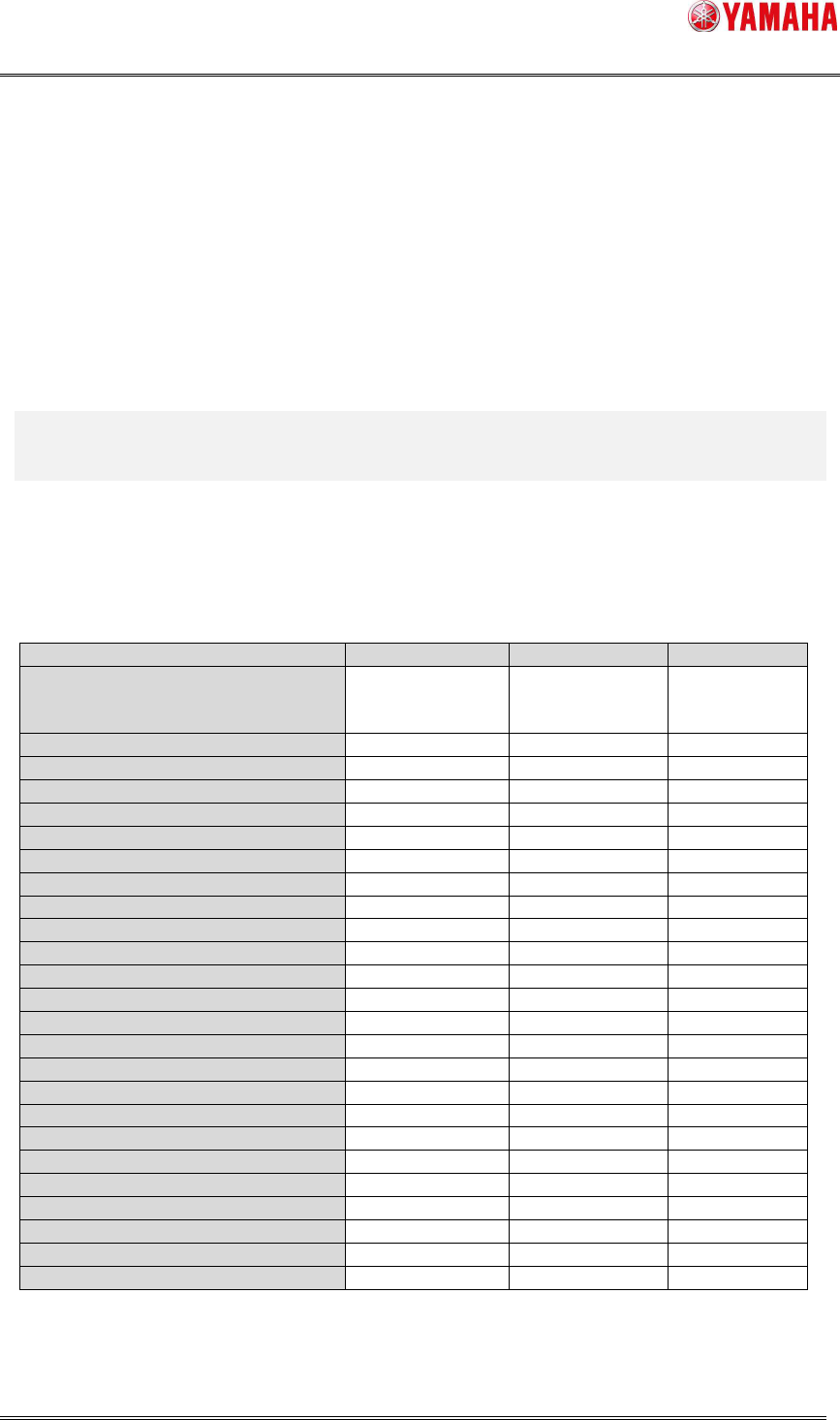
Each setting of [Parts Find Best Target] and auto-created parameters are as below.
Table3 Setting of [Parts Find Best Target] and auto-created parameters
Item Type,Size,Light
Size,Light Light
[Vision] – [Light Main]
[Vision] – [Light Coax]
[Vision] – [Light Side]
O (*1) O (*1) X
[Vision] – [Lighting Level] O O O
[Vision] – [Comp. Threshold] O O O
[Vision] – [Comp. Tolerance] O O X
[Vision] – [Search Area] O O O
[Vision] – [3D Threshold] O (*2) O (*2) O (*2)
[Vision] – [3D Main Lighting Level] O (*2) O (*2) O (*2)
[Vision] – [3D Coax Lighting Level] O (*2) O (*2) O (*2)
[Vision] – [3D Side Lighting Level] O (*2) O (*2) O (*2)
[Vision] – [3D Bright Area] O (*2) O (*2) O (*2)
[Shape] – [Alignment Type] O X X
[Shape] – [Base Alignment Type] O X X
[Shape] – [Algorithm] O X X
[Shape] – [Body Size X] O O X
[Shape] – [Body Size Y] O O X
[Shape] – [Ruler Offset (NSEW)] O O O
[Shape] – [Ruler Width] O O X
[Shape] – [Lead Group (NSEW)] O O X
[Shape] – [Lead Number (NSEW)] O O X
[Shape] – [Lead Pitch (NSEW)] O O X
[Shape] – [Lead Width (NSEW)] O O O (*3)
[Shape] – [ReflectLL (NSEW)] O O X
[Shape] – [Find Pos X (NSEW)] O O X
[Shape] – [Find Pos Y (NSEW)] O O X
[Shape] – [Vision Option (1~4)] O O X
(*1) For BGA parts, [Light Side] is turned ON if the side light is more applicable.
(*2) The items are created only when the parts are supported for co-planarity check and
SMT Software Engineering Group
IM Operations YAMAHA MOTOR CO., LTD
MDOC-SOFT50408
7/8
also when a value is set on [3D Co-Planarity Threshold].
(*3) Supported only for “Sp. Chip”, “Melf Chip”.
< Remarks >
* If auto-created parts size is too large to be recognized by the side view camera, [Parts] -
[Side View] - [Side View Camera] is automatically set to “Not Use”.
* Even when auto-created alignment type is not supported for co-planarity check, the
setting of [Parts] - [Vision] - [3D Co-Planarity Threshold] is not changed.
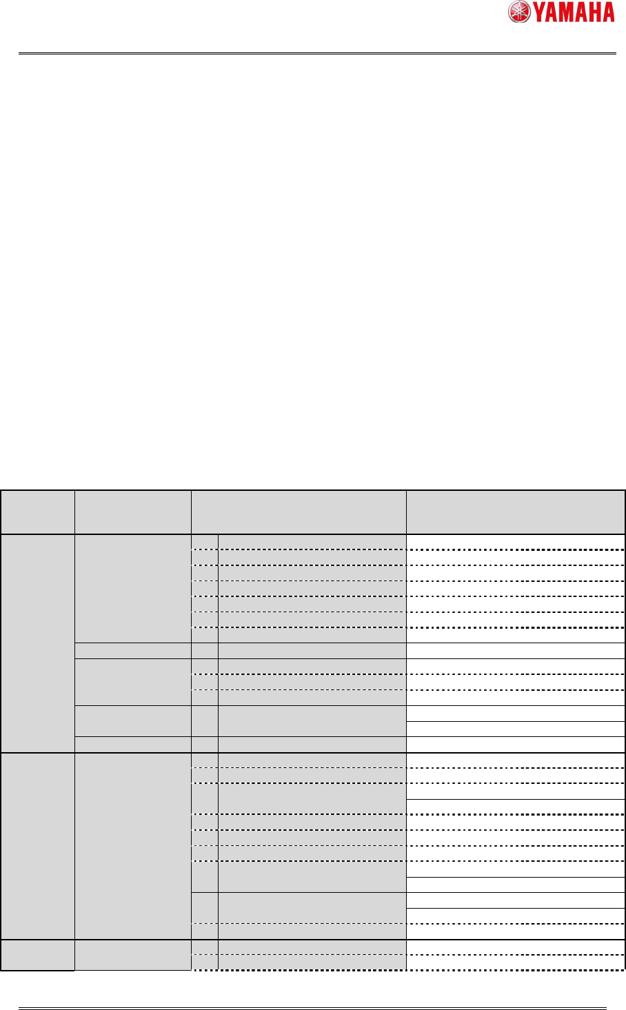
4.2 Alignment Type automatically created
Below is alignment types that may be created when [Parts Find Best Target] is set to
“Type,Size,Light”, and that can execute “Size,Light”. (If unsupported alignment type is
selected, items of “Size,Light” are not displayed in the [Parts Find Best Target] combo
box.)
Table4 Alignment Type automatically created
Alignment
Group
Alignment
Type
Algorithm
[Type,Size,Light]
O : support,
- : non-support
[Size,Light]
O : support,
- : non-support
Chip Std.Chip
2 Normal O O
1 Chamfer Lead - O
2 Check Lead Brightness - O
3 Check Direction - O
4 Check Center Brightness - O
5 Retry Lead Center Search - O
8 Chip Array - -
Melf Chip 0 Normal - O
Bare.Chip
0 Normal - O
12 Size Fitting - O
14 Small Bare Chip - -
Cylinder 0 Normal - -
Sp.Chip 0 Normal - O
Small Chip 2 Normal - -
Ball Simple BGA
0 Normal O O
1 Check Polarity - O
3 Simple White BGA - -
BGA
2 Normal O O
4 White BGA - -
7 CGA - O
10 Check Direction - O
12 Ball Circularity Check - O
Simple FlipChip
0 Normal - -
1 Outside Bump Recognition - -
FlipChip
2 Normal - -
3 Simple High Speed - -
IC 2Ends
0 Normal - O
3 Check Direction - O
SMT Software Engineering Group
IM Operations YAMAHA MOTOR CO., LTD
MDOC-SOFT50408
8/8
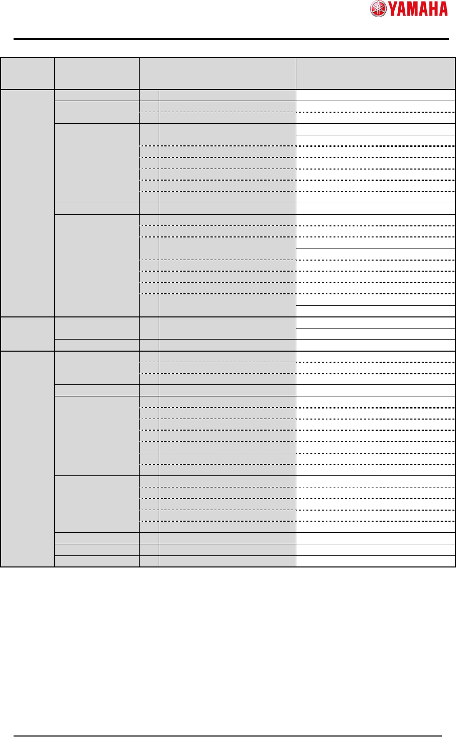
Alignment
Group
Alignment
Type
Algorithm
[Type,Size,Light]
O : support,
- : non-support
[Size,Light]
O : support,
- : non-support
10 Check Upside-Down - O
Mini-Tr/SOT
0 Normal O O
4 Check Upside-Down - O
P-Tr 0 Normal O O
SOP
0 Normal O O
1 Side Lead Fitting - O
5 Check Upside-Down - O
6 Check Global Lead Bend - -
7 Direction Check by Lead Width - O
8 Check Lead Position - O
SOJ 0 Normal O O
QFP
0 Normal O O
1 Side Lead Fitting - O
4 Check Lead Length - O
PLCC
0 Normal O O
1 Side Lead Fitting - O
2 NS Base Search - O
3 WE Base Search - O
4 Check Direction - O
OffLead 0 Normal - -
Connector Con-E 0 Normal O O
Con-NSEW 0 Normal O O
Odd.Con 0 Normal - O
Special Special
1 Side Lead Fitting - O
2 Long Connector - O
9 Insertion-Component - -
Odd.Chip 0 Normal - -
AsMark
0 Normal O O
1 Mark Line - O
2 2 Objects - O
3 4 Objects - O
4 General - O
6 Check Direction - O
8 2 Objects (Angle of Terminal) - O
Sp.Quad
0 Normal O O
3 Check Direction - O
8 Shield Frame - O
10 Check Upside-Down - O
11 4 Corner Fitting - -
Gravity 0 Normal - -
Ignore - - -
Smart Recognition - - -
* Random ball parts are not supported.