TK25947.Auto Create Parts Recognition Data.pdf - 第5页
SMT Software Engineering Group IM Operations Y AMAHA MOTOR CO., L TD MDOC-SOFT50408 5/8 When it is failed, execute the following procedures. If the part s are not defined with any existing algorithms, please…

SMT Software Engineering Group
IM Operations YAMAHA MOTOR CO., LTD
MDOC-SOFT50408
4/8
* For details of parameters automatically created, refer to Table 3.
* The [Parts Find Best Target] combo box is managed by operator’s level.
([Parts] - [Adjust Find Best Target] in the operator level edit screen)
3. Procedure of parts recognition data auto creation
3.1 Auto creation of alignment type and measurement data
If you don’t know which alignment type to select, execute auto creation of alignment type
and measurement data through the following procedure.
(1) Parts basic data
On the [Parts] screen, select parts data and enter the following information.
[Basic] tab ・・・ [Required Nozzle], [Package], [Feeder Type] etc.
[Pick] tab ・・・ [Feeder Set No.] etc.
[Shape] tab ・・・ [Body Size X], [Body Size Y], [Body Size Z]
* [Body Size X] and [Body Size Y] are used to roughly decide the camera area, so that
they don’t need to be exact values.
* The first image is applied with Light Main=ON, Light Coax=ON, and Lighting Level=7/8.
Therefore, you don’t need to make lighting settings for that.
(2) Pick up
Press the [PartsAdj] button to open the [Parts Adjust] screen. Specify a head number and
press the [Pick Up] button, so that the head picks up the parts.
(3) Decide alignment type
Set [Parts Find Best Target] to “Type,Size,Light”, and press the [Find Best] button.
[Alignment Type] and [Body Size] are automatically defined based on the parts image, and
parameters of [Lighting Level] and [Comp. Threshold] are tuned.
(4) Completion
When it is successfully completed, “Vision parameters optimized” is displayed in the result
area. [Body Size] after [Find Best] is displayed on the grid above. (Change of Body Size is
not displayed in the result area.) Also, [Monitor Mode] is automatically switched to
“Defined Shape”, and a parts recognition image and a defined shape are overlaid on the
vision window.

SMT Software Engineering Group
IM Operations YAMAHA MOTOR CO., LTD
MDOC-SOFT50408
5/8
When it is failed, execute the following procedures. If the parts are not defined with any
existing algorithms, please use the Smart Recognition function.
(a) When a whole parts body is not within the view, make [Body Size X] and [Body Size
Y] larger.
(b) When the view is out of focus, change the value of [Body Size Z].
(c) Select alignment type by hand, and create body size automatically. (Refer to 3.2)
3.2 Auto creation of Body Size without changing Alignment Type
To create only body size and lead data without changing alignment type, execute auto
creation of body size through the following procedure.
(1) Parts basic data
On the [Parts] screen, select parts data and enter the following information.
[Basic] tab ・・・ [Required Nozzle], [Package], [Feeder Type] etc.
[Pick] tab ・・・ [Feeder Set No.] etc.
[Shape] tab ・・・ [Body Size X], [Body Size Y], [Body Size Z]
* [Body Size X] and [Body Size Y] are used to roughly decide the camera area, so that they
don’t need to be exact values.
* The first image is applied with Light Main=ON, Light Coax=ON (When “Alignment Type”
is “Simple BGA” or “BGA”, Light Side=ON), and Lighting Level=7/8. Therefore, you
don’t need to make lighting settings for that.
(2) Pick up
Press the [PartsAdj] button to open the [Parts Adjust] screen. Specify a head number and
press the [Pick Up] button, so that the head picks up the parts.
(3) Execution of “Measurement size”
Set [Parts Find Best Target] to “Size,Light”, and press the [Find Best] button. [Body Size]
is automatically defined based on the parts image, and parameters of [Lighting Level] and
[Comp. Threshold] are tuned.
(4) Completion
When it is successfully completed, “Vision parameters optimized” is displayed in the result
area. [Body Size] after [Find Best] is displayed on the grid above. (Change of Body Size is
not displayed in the result area.) Also, [Monitor Mode] is automatically switched to
“Defined Shape”, and a parts recognition image and a defined shape are overlaid on the
SMT Software Engineering Group
IM Operations YAMAHA MOTOR CO., LTD
MDOC-SOFT50408
6/8
vision window.
If it is failed, execute the following procedures. If the parts are not defined with any
existing algorithms, please use the Smart Recognition function.
(a) When a whole parts body is not within the view, make [Body Size X] and [Body Size
Y] larger.
(b) When the view is out of focus, change the value of [Body Size Z].
(c) Set alignment type to be a target of auto creation. (Refer to 3.1)
4. Function Details
4.1 Auto-created parameter
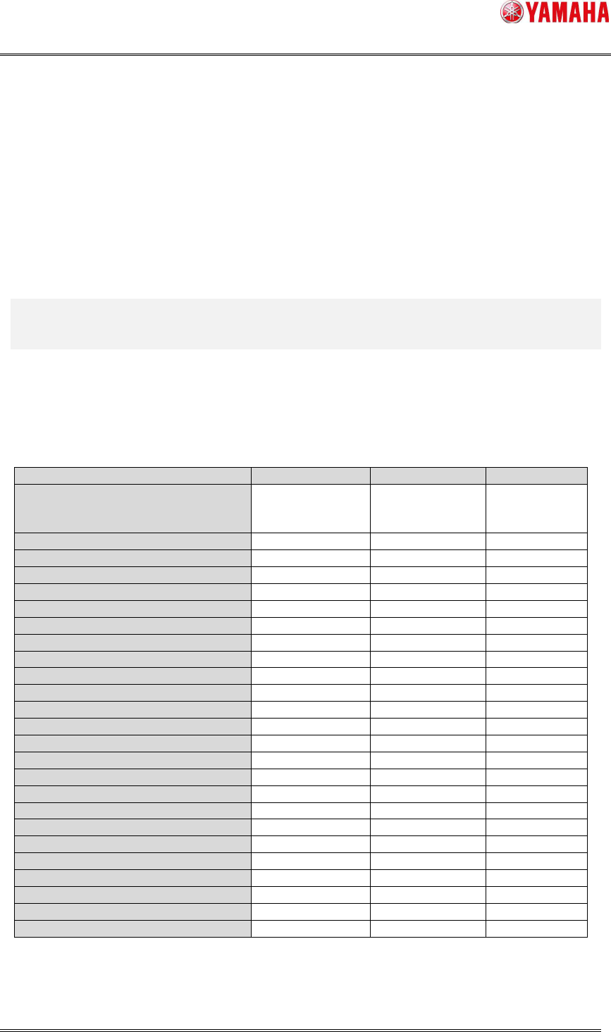
Each setting of [Parts Find Best Target] and auto-created parameters are as below.
Table3 Setting of [Parts Find Best Target] and auto-created parameters
Item Type,Size,Light
Size,Light Light
[Vision] – [Light Main]
[Vision] – [Light Coax]
[Vision] – [Light Side]
O (*1) O (*1) X
[Vision] – [Lighting Level] O O O
[Vision] – [Comp. Threshold] O O O
[Vision] – [Comp. Tolerance] O O X
[Vision] – [Search Area] O O O
[Vision] – [3D Threshold] O (*2) O (*2) O (*2)
[Vision] – [3D Main Lighting Level] O (*2) O (*2) O (*2)
[Vision] – [3D Coax Lighting Level] O (*2) O (*2) O (*2)
[Vision] – [3D Side Lighting Level] O (*2) O (*2) O (*2)
[Vision] – [3D Bright Area] O (*2) O (*2) O (*2)
[Shape] – [Alignment Type] O X X
[Shape] – [Base Alignment Type] O X X
[Shape] – [Algorithm] O X X
[Shape] – [Body Size X] O O X
[Shape] – [Body Size Y] O O X
[Shape] – [Ruler Offset (NSEW)] O O O
[Shape] – [Ruler Width] O O X
[Shape] – [Lead Group (NSEW)] O O X
[Shape] – [Lead Number (NSEW)] O O X
[Shape] – [Lead Pitch (NSEW)] O O X
[Shape] – [Lead Width (NSEW)] O O O (*3)
[Shape] – [ReflectLL (NSEW)] O O X
[Shape] – [Find Pos X (NSEW)] O O X
[Shape] – [Find Pos Y (NSEW)] O O X
[Shape] – [Vision Option (1~4)] O O X
(*1) For BGA parts, [Light Side] is turned ON if the side light is more applicable.
(*2) The items are created only when the parts are supported for co-planarity check and