6-7-p0213-0230-kk-kkh_en.pdf - 第15页
KK KKH KKA KK130 Series KK KKH KKA KK130 1. For a pl ug and socket connection , select a plu g and socket with the same bo dy siz e. If their body sizes are different, they cannot be connected. This will caus…
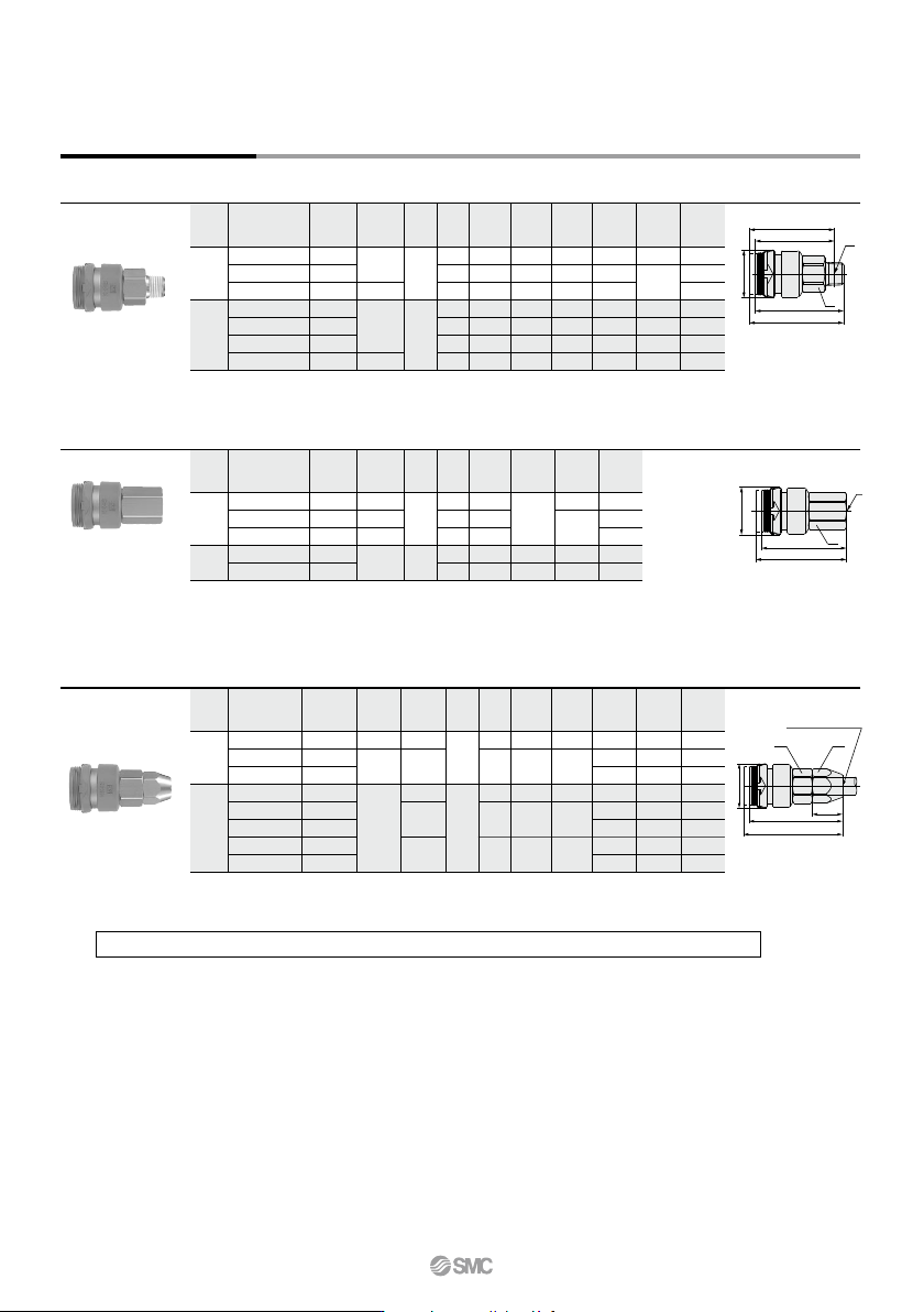
Body
size
Weight
g
Effective
area
mm
2
L1
Min.
bore
size
1/8
1/4
14
17
19
22
R 1/8
R 1/4
R 3/8
R 1/8
R 1/4
R 3/8
R 1/2
20.2
28.0
L2
When
connected
36.0
34.0
34.5
50.1
48.7
47.2
45.4
6.0
9.0
9.0
6.0
9.0
11.0
13.0
20.4
21.1
22.9
38.9
40.4
42.7
20.3
19.4
27.7
48.7
45.3
52.1
62.4
33.5
31.5
32.2
46.4
45.0
43.5
41.7
39.1
39.5
40.1
53.2
54.2
52.6
52.5
36.6
37.0
37.6
49.5
50.5
48.9
48.8
Model
KKH3S-01MS
-02MS
-03MS
KKH4S-01MS
-02MS
-03MS
-04MS
A1
∗
A
2
∗
When
connected
(mm)
H
Width
across flats
T
Connection
port size
øD
Male thread type
Body
size
Weight
g
Effective
area
mm
2
L1
Min.
bore
size
1/8
1/4
Rc 1/8
Rc 1/4
Rc 3/8
Rc 1/4
Rc 3/8
36.0
40.1
41.9
50.4
51.1
38.5
42.4
44.3
54.1
54.8
14
17
19
19
20.2
28.0
L2
When
connected
8.2
10.9
14.4
20.6
21.1
39.6
42.7
23.8
33.1
37.1
58.1
47.4
Model
KKH3S-01F
-02F
-03F
KKH4S-02F
-03F
(mm)
H
Width
across flats
T
Connection
port size
øD
Female thread type
Body
size
Weight
g
Effective
area
mm
2
L1
Min.
bore
size
1/8
1/4
5/8
6/9
6.5/10
5/8
6/9
6.5/10
8/12
8.5/12.5
14
17
19
14
17
14
17
19
M
20.2
28.0
L2
When
connected
4.5
5.4
5.9
4.5
5.4
5.9
7.4
7.8
42.6
44.4
54.1
56.8
55.4
45.1
46.9
57.8
60.5
59.1
13.7
16.5
13.7
16.5
17.4
12.2
18.3
19.2
12.2
20.4
24.1
35.1
36.6
32.3
48.9
46.6
57.0
70.5
68.0
69.7
72.3
Model
KKH3S-50N
-60N
-65N
KKH4S-50N
-60N
-65N
-80N
-85N
(mm)
H1
Width
across flats
H2
Width
across flats
øD
Applicable
hose
I.D./O.D.
Nut fitting type (for fiber reinforced urethane hose)
∗ Reference dimension for R threads after installation.
Dimensions/Socket (S)
KKH series are only available as sockets. KK series should be used as plugs. For dimensions, please refer to page 220.
A1
A2
L1
L2
øD
L2
M
L1
øD
H1 H2
H
T
L1
L2
øD
H
T
Applicable hose
KKH Series
226
KK
KKH
KKA
KK130
Series
KK
KKH
KKA
KK130
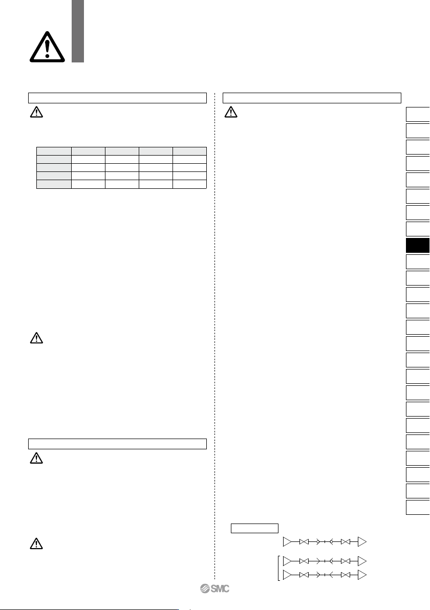
1. For a plug and socket connection, select a plug and
socket with the same body size. If their body sizes are
different, they cannot be connected. This will cause
leakage, damage, and disconnection of the plug.
Inserting a plug other than the specialized plug into the
socket may result in equipment damage.
2. Do not use couplers with flammable, explosive, or toxic
substances, such as gas, gas fuel, and refrigerant. They
may leak from inside the tubing to the outside.
3. Do not use the S coupler with steam. Corrosion of the
metal material and deterioration of the sealing material
may result from long-term use with steam.
1. Do not use couplers where rotation normally occurs. The
couplers may be damaged.
2. Avoid applications in which vibration or shock is directly
applied to the fittings.
3. Fittings with sleeve lock mechanism must be locked
during operation in order to prevent sudden disconnection.
4. Install a stop valve at the supply pressure side of the
socket. Emergency shutdown may not be possible
without it.
1. Mount so that couplers and tubing are not subjected to
twisting, pulling or moment loads. This can cause
damage to couplers and flattening, bursting or disconnec-
tion of tubing, etc.
S Couplers
Specific Product Precautions 1
Be sure to read this before handling the products.
Refer to back page 50 for Safety Instructions and pages 13 to 17 for Fittings and
Tubing Precautions.
Selection
Mounting
Warning
Warning
Caution
Caution
1. Cannot be used as a stop valve that requires zero leakage.
A certain amount of leakage is allowed during operation.
2.
S coupler connection possibilities are shown in the table below.
∗ Before using a KK130 series S coupler with another
manufacturer’s product, be sure to confirm compatibility
with the manufacturer, etc.
3. Do not couple or uncouple the S coupler during pressur-
ization or while residual pressure remains. The coupler
may shoot out under the influence of the pressure.
4. Never apply pressure to an S coupler without check valve
when it is uncoupled. The piping may move violently and
cause danger.
5. An S coupler without check valve experiences leakage of
fluid inside piping when it is uncoupled. Pay special
attention in using fluid that can cause danger such as
fluid of a high temperature and pressure. Additional use
of a stop valve is recommended.
6. The S coupler becomes extremely hot when the product
is operated at a high temperature. Be sure to refrain from
touching it as doing so may result in burns. Insert or
remove the plug and socket only after the product has
returned to a normal temperature.
Warning
Handling
1. When connecting the plug, hold the plug securely.
The plug may be uncoupled due to reaction at the time of
connection.
2.
When connecting KK, KKH, and KKA series plugs, push the plug
in until you hear it click into the socket. In addition, be sure to
refrain from touching the sleeve until you are sure that the plug
has been pushed all the way in. Failure to do so may result in a
malfunction. When connecting KK130 series plugs, after pulling
the sleeve straight back, push the plug in until you are sure that
it has been pushed all the way in. For all S couplers, after
inserting the plug, pull on it gently to make sure that it doesn’t
come out from the socket. If the plug is not properly inserted into
the socket, the plug may fly out of the product due to pressure.
3. When connecting the plug, insert it straight into the
socket. If not inserted straight, the socket and/or plug
may be damaged or cause a malfunction.
4. When releasing the plug, hold it securely. The connection
pipe may move due to reacting stress and/or residual
pressure on the plug side.
5. Be sure to move the sleeve straight in relation to the
socket. If it is rotated at all, a malfunction may result.
6. Do not press the inside of the socket with an incompatible
plug and/or with a stick. The internal fluid may be ejected
and cause a dangerous situation. Also, the ejecting
internal fluid may cause the sealings to come apart
resulting in the product not functioning.
7.
If foreign matter adheres to the plug O-ring, be sure to wipe it
off. If air blow is performed with the air gun air outlet in close
proximity to the plug O-ring, the plug O-ring may come off.
8.
For products with a sleeve lock mechanism, do not apply
pressure when rotating the sleeve. If the KK130 series is
pressurized during rotation, the detent of the locked and
released positions may become unclear due to the pressure.
In addition, operate the product in accordance with the arrows
on the sleeve surface. Failure to do so may result in problems
with the attaching and detaching of the mechanism.
9.
If the plug and socket cannot be separated due to a
malfunction of the sleeve, do not try to forcibly pull out the
plug. Instead, turn the sleeve clockwise (viewed from the
plug insertion side) 3 to 5 times, and then check to see if the
sleeve moves properly. If the sleeve still doesn’t move
properly, try turning it counter-clockwise in the same
manner, and check it again.
If the aforementioned method fails to work, loosen the plug
and socket connection thread and remove it from the piping.
10.
Water is an incompressible fluid. Design the piping while taking the
characteristics of the fluid into consideration.
If the plug or socket piping of the type with a check valve is filled
with water and the valve above said piping is closed, removing the
plug or socket will result in the piping between the check valve and
the closed valve filling with water. (Refer to the circuit example.)
In order to reinsert the plug or socket while in the aforementioned
state, the water would need to be compressed to allow room for
the plug or socket. However, as this is not possible, the plug and
socket cannot be reinserted while in this state.
Circuit example
Connected plug and socket
Check valve
on both sides:
Check valve
on single side:
Water supply
Valve Valve Drain
227
KQ2
KQB2
KS
KX
KM
KF
M
H/DL
L/LL
KC
KK
KK130
DM
KDM
KB
KR
KA
KQG2
KG
KFG2
MS
KKA
KP
LQ
MQR
T
IDK
KK
E
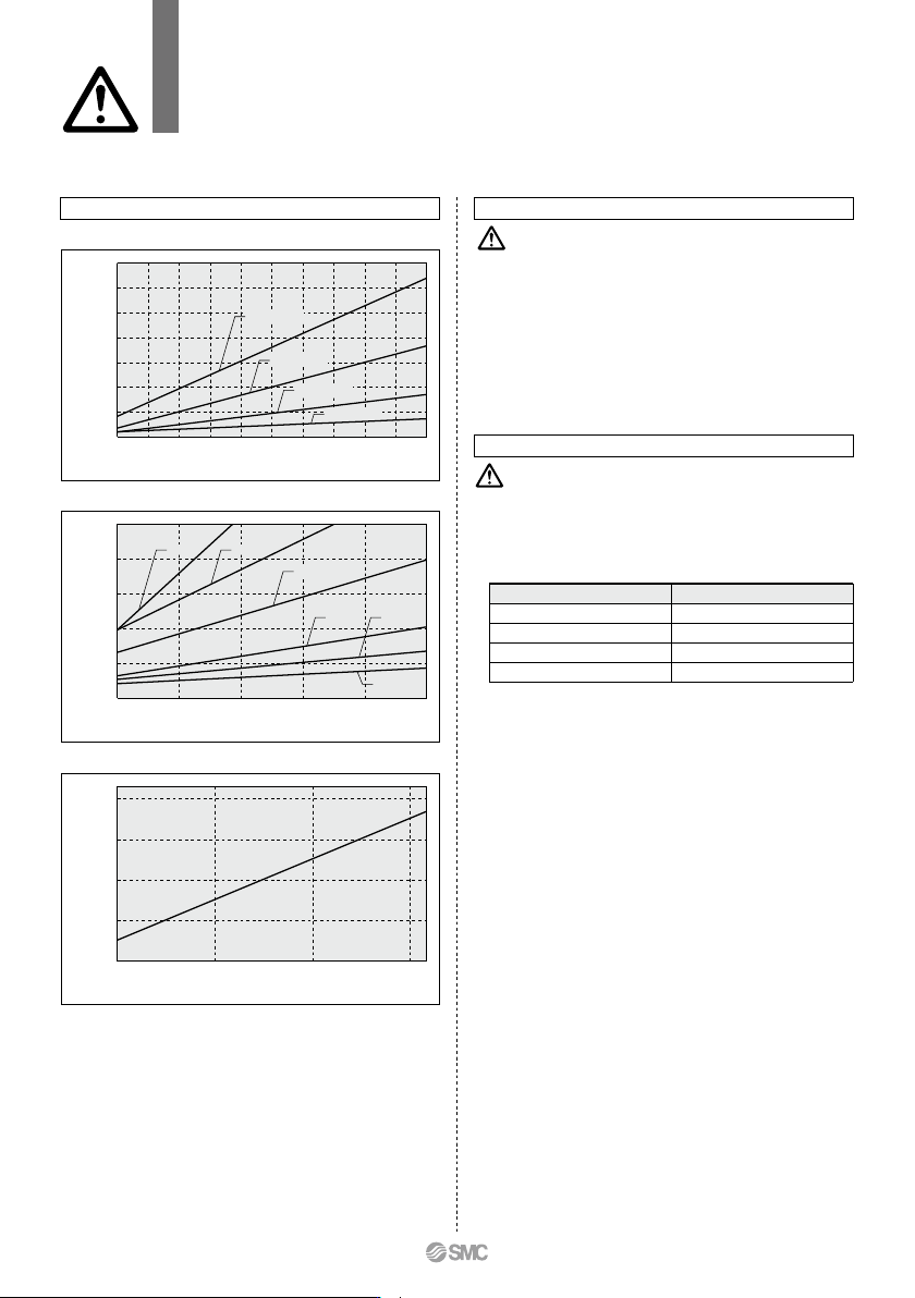
200
150
100
50
0
0
Charging pressure MPa
0.5 1.5
Insertion force N
1
S Couplers
Specific Product Precautions 2
Be sure to read this before handling the products.
Refer to back page 50 for Safety Instructions and pages 13 to 17 for Fittings and
Tubing Precautions.
Insertion Force of KKA series
500
400
300
200
100
0
0 0.1 0.2 0.3 0.4 0.5
Charging pressure MPa
Insertion force N
KKA9 KKA8
KKA7
KKA6 KKA4
KKA3
Plug Insertion Force in Pressurized Condition
Insertion Force of KK series
350
300
250
200
150
100
50
0
0 0.1 0.2 0.3 0.4 0.5 0.6 0.7 0.8 0.9 1
Charging pressure MPa
Insertion force N
KK6 series
KK4 series
KK3 series
KK2 series
Insertion Force of KK130 series
Handling of Barb Fittings and Nut Fittings
Caution
1. When using a nut fitting, insert the hose all the way to the
end and securely tighten it with the nut. When the inser-
tion of the hose or the tightening of the nut are not
sufficient, the hose may slip out.
2. Disconnection may occur depending on the material or
the O.D. accuracy of the hose; therefore be sure to
confirm the applicability of the hose.
3. Prepare a hose band separately when using a barb fitting.
If the hose band is not used, the hose may come off.
1. Tightening of the fittings with a sealant
Tighten fittings with sealant using the proper tightening
torques in the table below. As a rule, they should be
tightened 2 to 3 turns with a tool after first tightening by
hand.
Handling of Fittings
Caution
Connection thread size
NPT, R 3/4
NPT, R 1
NPT, R 1 1/4
NPT, R 1 1/2
Proper tightening torque N·m
28 to 30
36 to 38
40 to 42
48 to 50
228
B