Nordson-EFD-736HPA-NV-Operating-Manual.pdf - 第3页
736HPA-NV | Operating Manual 3 www.nordsonefd.com info@nordsonefd.com +1-401-431-7000 Sales and service of Nordson EFD dispensing systems are available worldwide. Contents ................................................…

736HPA-NV | Operating Manual
2 www.nordsonefd.com info@nordsonefd.com +1-401-431-7000 Sales and service of Nordson EFD dispensing systems are available worldwide.
You have selected a reliable, high-quality dispensing system from Nordson EFD, the world leader in fluid
dispensing. The 736HPA-NV valve was designed specifically for industrial dispensing and will provide you with
years of trouble-free, productive service.
This manual will help you maximize the usefulness of your 736HPA-NV valve.
Please spend a few minutes to become familiar with the controls and features. Follow our recommended testing
procedures. Review the helpful information we have included, which is based on more than 50years of industrial
dispensing experience.
Most questions you will have are answered in this manual. However, if you need assistance, please do not
hesitate to contact EFD or your authorized EFD distributor. Detailed contact information is provided on the last
page of this document.
The Nordson EFD Pledge
Thank You!
You have just purchased the world’s finest precision dispensing equipment.
I want you to know that all of us at Nordson EFD value your business and will do everything in our power to
make you a satisfied customer.
If at any time you are not fully satisfied with our equipment or the support provided by your Nordson EFD
Product Application Specialist, please contact me personally at 800.556.3484 (US), 401.431.7000 (outside US),
or Ferran.Ayala@nordsonefd.com.
I guarantee that we will resolve any problems to your satisfaction.
Thanks again for choosing Nordson EFD.
Ferran Ayala, Vice President
Ferran
736HPA-NV | Operating Manual
3www.nordsonefd.com info@nordsonefd.com +1-401-431-7000 Sales and service of Nordson EFD dispensing systems are available worldwide.
Contents ...................................................................................................................................................................................... 3
Introduction ................................................................................................................................................................................. 3
How the Valve Operates .............................................................................................................................................................. 4
Valve Stroke Adjustment ............................................................................................................................................................. 4
How the Valve is Controlled ........................................................................................................................................................ 5
Specifications .............................................................................................................................................................................. 6
Operating Features ...................................................................................................................................................................... 6
Installation ................................................................................................................................................................................... 7
Service ......................................................................................................................................................................................... 8
Valve Part Numbers ..................................................................................................................................................................... 8
Accessories ................................................................................................................................................................................. 8
Replacement Parts ...................................................................................................................................................................... 8
Troubleshooting .......................................................................................................................................................................... 9
Contents
Introduction
This manual provides specifications, operating, installation, and
troubleshooting information for the 736HPA-NV high pressure dispense
valve.
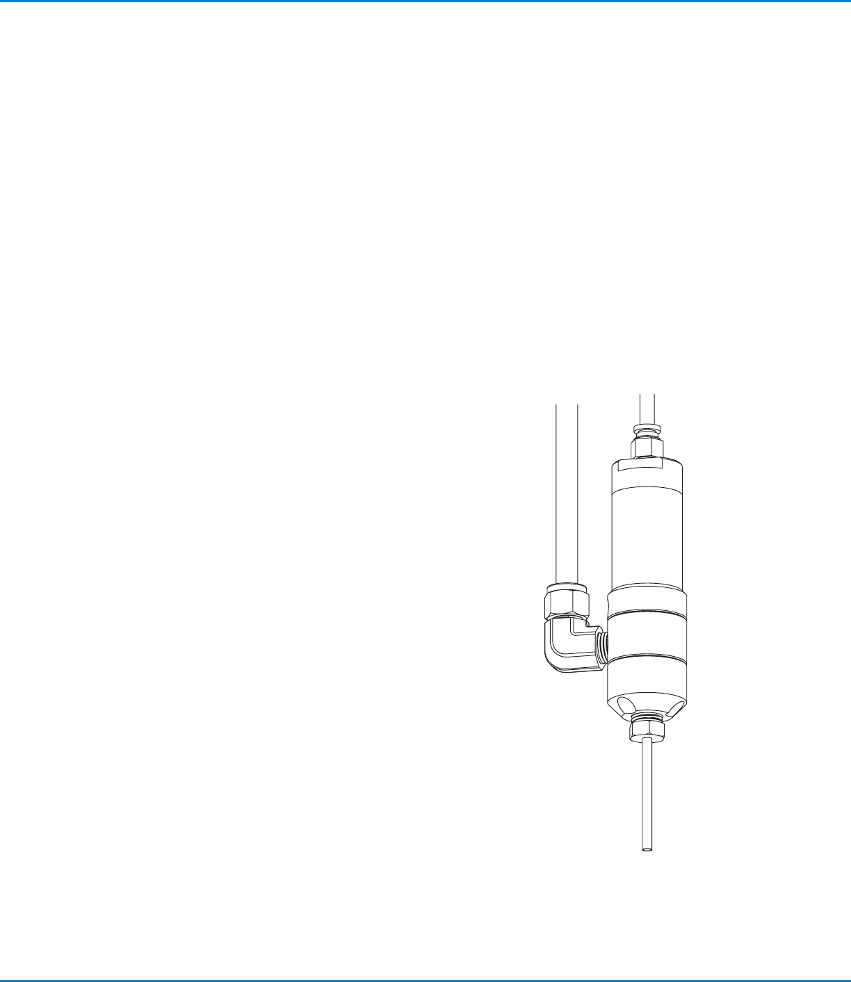
The 736HPA-NV is a normally closed, air-actuated, balanced spool-type
valve designed to operate at fluid pressures up to 172 bar (2500psi). Ideal
for consistent dispensing of industrial sealants and greases, the 736HPA-NV
valve is simple to use and will operate many millions of cycles without wear
or leakage.
736HPA-NV | Operating Manual
4 www.nordsonefd.com info@nordsonefd.com +1-401-431-7000 Sales and service of Nordson EFD dispensing systems are available worldwide.
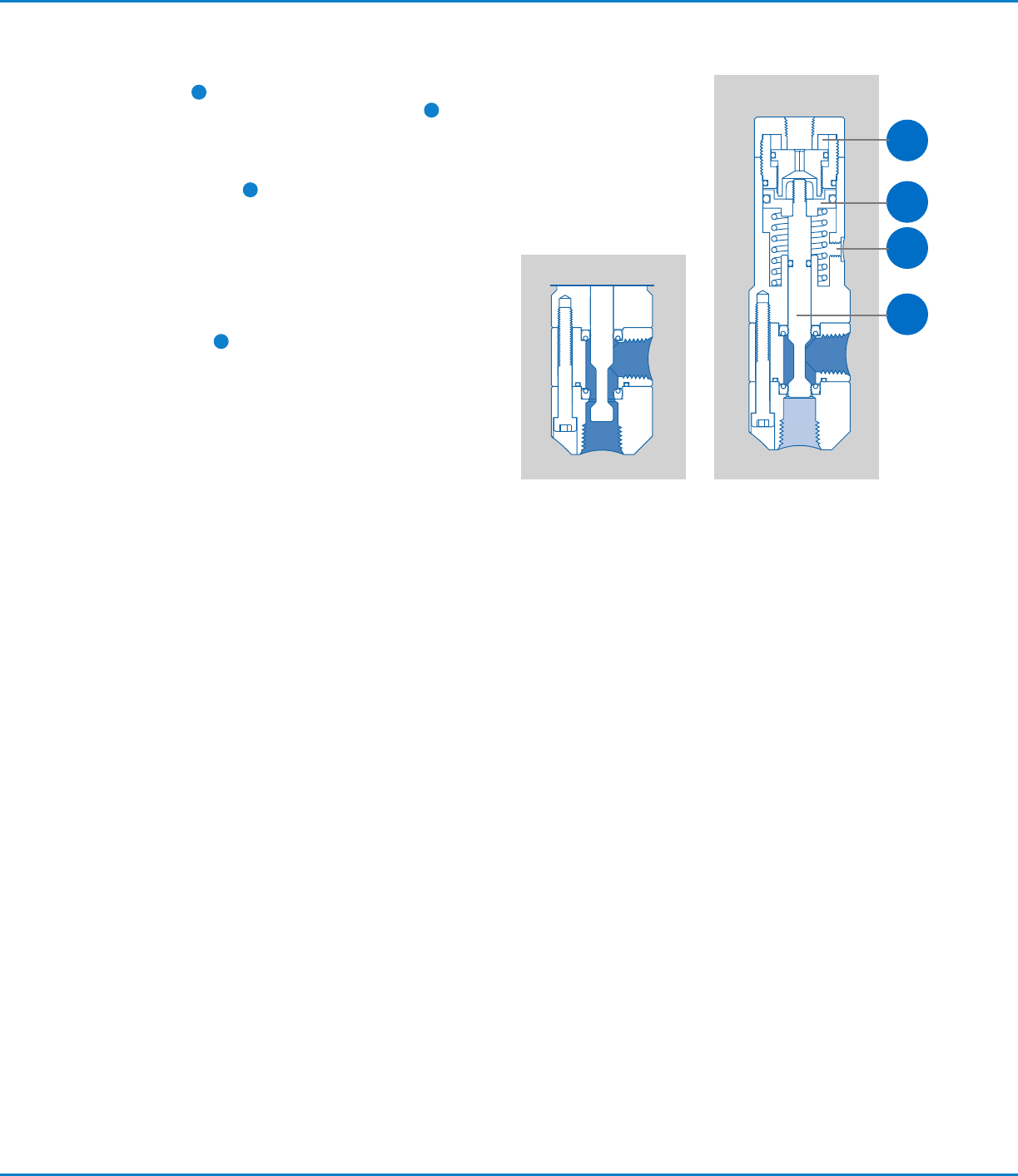
How the Valve Operates
When air pressure at 4.8 bar (70 psi) is applied, the piston
shifts the shaft
1
to the open position, allowing fluid to flow.
At the end of the cycle, spring force on the piston
2
shifts
the shaft to the closed position, stopping fluid flow. During
the closing action, the 736HPA-NV valve provides snuff-back
of fluid for clean cutoff.
The stroke adjustment
3
can be used to regulate the
snuff-back to an amount appropriate for the fluid being
dispensed. Stroke adjustment can also be used to reduce
fluid surge when the valve opens to ensure consistent bead
widths and dot profiles. Refer to “Valve Stroke Adjustment”
below for instructions.
When dispensing very thick fluids at high cycle rates, the
double-acting feature ensures rapid closure. A double-
actuating air input
4
is provided on the side of the air
cylinder to allow double-acting operation using air pressure
to both open and close the valve.
The amount of fluid dispensed is determined by valve open-
time, fluid pressure, dispensing tip size, and fluid viscosity.
ClosedOpen
2
3
4
1
Valve Stroke Adjustment
The stroke is adjusted by moving the stroke limit stop. You
will need a 5/64" hex wrench to adjust the valve stroke.
1. To access the stop, first remove the air input hose from
the push-in air coupling by pushing down on the release
ring while pulling up on the tubing.
2. Insert a 5/64" hex wrench through the air coupling and
engage the stroke limit stop.
3. Adjust the stop toward or away from the piston to vary
the stroke:
• To decrease the amount of opening surge and closing
snuff-back, extend the limit stop by turning the wrench
clockwise.
• To increase the amount of surge and snuff-
back, retract the limit stop by turning the wrench
counterclockwise.
NOTE: Adjusting the stroke does not affect the flow rate.
4. Reinstall the air input hose by pushing the hose into the
coupling.
NOTE: For striping applications, fluid surge can be
reduced further by lowering the valve operating air
pressure down to, but not below, 2.7 bar (40 psi).