Nordson-EFD-736HPA-NV-Operating-Manual.pdf - 第8页
736HPA-NV | Operating Manual 8 www.nordsonefd.com info@nordsonefd.com +1-401-431-7000 Sales and service of Nordson EFD dispensing systems are available worldwide. Accessories 1/4 NPT Metal Nozzles Stainless steel, 38.1 m…
736HPA-NV | Operating Manual
7www.nordsonefd.com info@nordsonefd.com +1-401-431-7000 Sales and service of Nordson EFD dispensing systems are available worldwide.
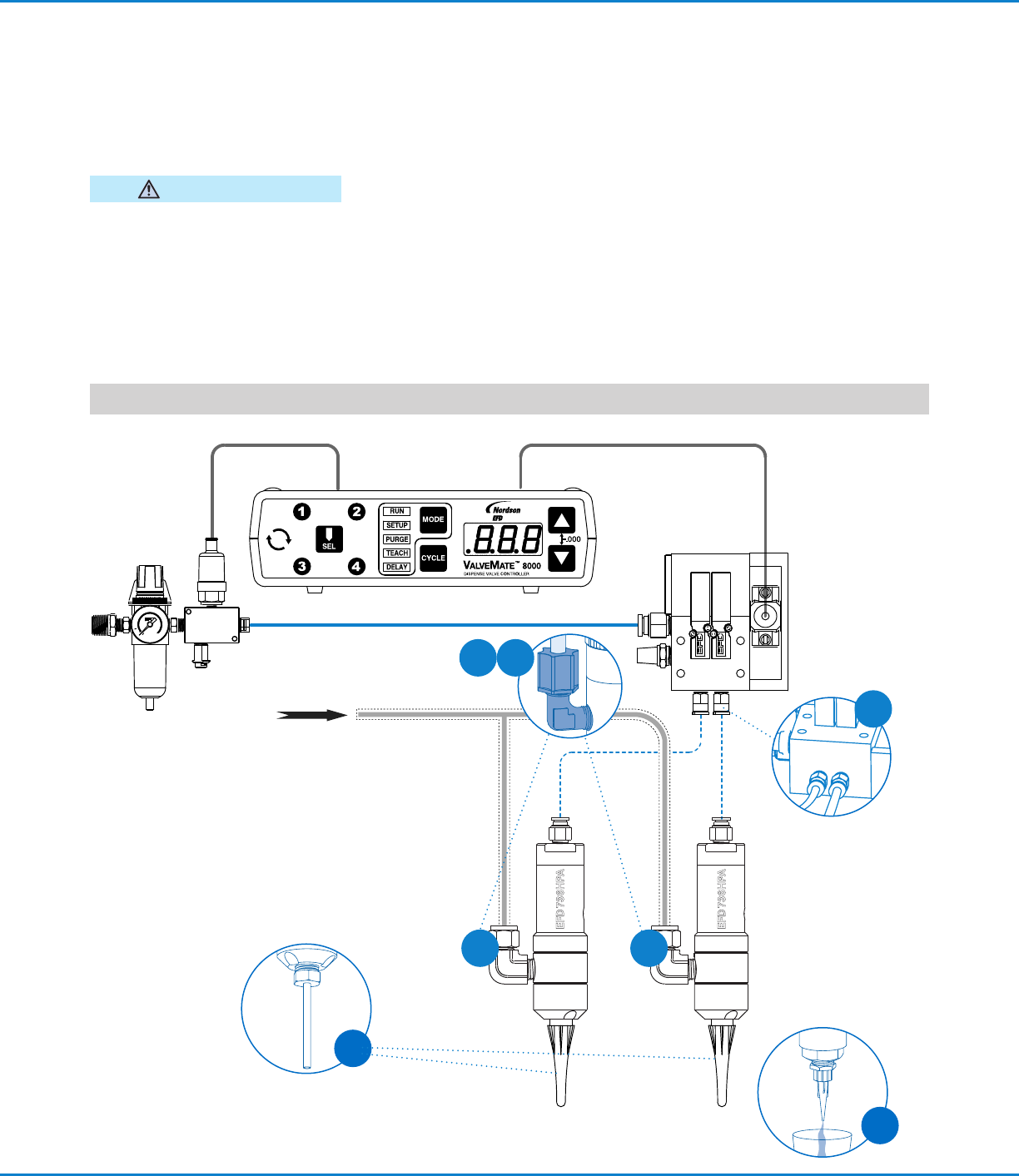
Installation
Prior to installing this valve, read the
associated reservoir and valve controller
operating instructions to become familiar
with the operation of all components of the
dispensing system.
Do not thread fluid inlet fittings too far
into the valve. Doing so can obstruct
the piston shaft, causing leakage, poor
dispensing performance, and damage to
the valve.
CAUTION
1. Thread the fluid inlet fitting into the fluid
inlet hole.
NOTE: The fluid inlet fitting and hose
must be obtained from a high pressure
pump supplier. Ensure that the hose
and fitting are rated for the maximum
operating pressure of the pump system.
2. Connect the fluid feed hose to the
fitting.
3. Connect the valve control air hose to the
ValveMate 8000 controller solenoid pack
used to control valve open time.
4. Install an appropriate threaded nozzle
on the valve output or use a dispensing
tip adapter (#7016941) with EFD
SafetyLok
™
dispensing tips.
5. Ensure that all fluid and air connections
are tight.
6. Ensure that the valve operating pressure
is set at 4.8 bar (70 psi).
7. Ensure that the delivery pump pressure
does not exceed 172 bar (2500 psi).
8. Place a cup under the dispensing tip or
nozzle and actuate the valve until fluid
flows steady.
9. Set the desired flow rate by adjusting
the fluid pressure or changing the outlet
tip size.
NOTE: Set the desired deposit size by adjusting the valve open time. Refer to the valve controller operating manual.
3
8
4
1
1
21
From fluid reservoir

736HPA-NV | Operating Manual
8 www.nordsonefd.com info@nordsonefd.com +1-401-431-7000 Sales and service of Nordson EFD dispensing systems are available worldwide.
Accessories
1/4 NPT Metal Nozzles
Stainless steel, 38.1 mm (1.5") long. ID Size
Part # Gauge mm (in.)
7014850 7 3.81 (0.150)
7014851 8 3.43 (0.135)
7014848 10 2.69 (0.106)
7014842 12 2.16 (0.085)
7014844 14 1.60 (0.063)
7014846 16 1.20 (0.047)
Polyethylene Nozzles
Plastic nozzles with 1/4 NPT thread. Nozzles may be cut
or shaped as required. Supplied (10) nozzles per package.
Part # Size
7018555 63.5 mm long x 3.2 mm
opening (2 1/2" x 1/8")
7018557 63.5 mm long x 1.6 mm
opening (2 1/2" x 1/16")
7018559 101.6 mm long x 1.6 mm
opening (4" x 1/16")
7018561 101.6 mm long x 0.8 mm
opening (4" x 1/32")
Dispensing Tip Adapter
Accepts all EFD dispensing tips.
Part # Description
7021197 Adapter for use with metal tips
7021186 Adapter for use with disposable plastic tips
Universal Valve Mount
Use with all EFD valves for easy valve mounting.
Part # Description
7020507 Universal valve mount
Accessories (continued)
Service
Refer to the 736HPA-NV Service & Replacement Parts Manual for service procedures, including valve disassembly /
reassembly.
Valve Part Numbers
Part # Description
7013449 736HPA-NV valve, chromium-plated spool
7028951 736HPA-NV valve, titanium nitride-coated spool
Replacement Parts
Refer to the 736HPA-NV Service & Replacement Parts Manual for kits that include replacement parts.

736HPA-NV | Operating Manual
9www.nordsonefd.com info@nordsonefd.com +1-401-431-7000 Sales and service of Nordson EFD dispensing systems are available worldwide.
No fluid flow
• If the valve operating pressure is too low, the valve will
not open. Increase air pressure to 4.8 bar (70psi) for
timed shots and to 2.7 bar (40 psi) minimum for stripes.
• The fluid pressure may not be high enough. Increase
pressure.
• The dispensing tip may be clogged. Replace tip.
• Fluid may have solidified in the fluid body. Clean the fluid
body.
Fluid drools after the valve closes, eventually
stopping
• This is caused by air trapped in the outlet section of the
fluid body or if the fluid has entrapped air. The air will
expand after the valve closes, causing extrusion until the
air reaches atmospheric pressure. Purge the valve by
dispensing at a steady flow until air is removed.
• If the fluid has entrapped air, degas it before dispensing.
Fluid drips at a steady rate after the valve
closes
• A steady drip indicates failure of the seal due to particle
build-up or wear. Replace the seal.
• Fluid leakage can also occur when a fluid inlet fitting
is threaded too far into the valve, thus obstructing the
piston shaft. Ensure that the fluid inlet fitting is properly
installed.
Valve responds slowly when opening and
closing
• Valve response is related to control air line length and
size. EFD valves are supplied with 5 feet of 4mm (5/32")
ID tubing attached. Any additional length or size change
will affect response time. Ensure that the length and size
have not been changed.
Fluid flows out above upper seal
• Fluid flowing out above the upper seal indicates a worn
upper seal. Replace the seal.
Inconsistent deposits
• Inconsistent deposits can result if the air pressure
controlling the valve and / or fluid pressure is fluctuating,
or if the valve operating pressure is less than 4.8bar
(70 psi). Check air pressures and the valve operating
pressure.
• The time the valve is open must be consistent. Ensure
that the valve controller is providing a consistent output.
Troubleshooting