Nordson-EFD-736HPA-NV-Operating-Manual.pdf - 第5页
736HPA-NV | Operating Manual 5 www.nordsonefd.com info@nordsonefd.com +1-401-431-7000 Sales and service of Nordson EFD dispensing systems are available worldwide. How the V alve is Contr olled The ValveMate ™ 8000 provid…
736HPA-NV | Operating Manual
4 www.nordsonefd.com info@nordsonefd.com +1-401-431-7000 Sales and service of Nordson EFD dispensing systems are available worldwide.
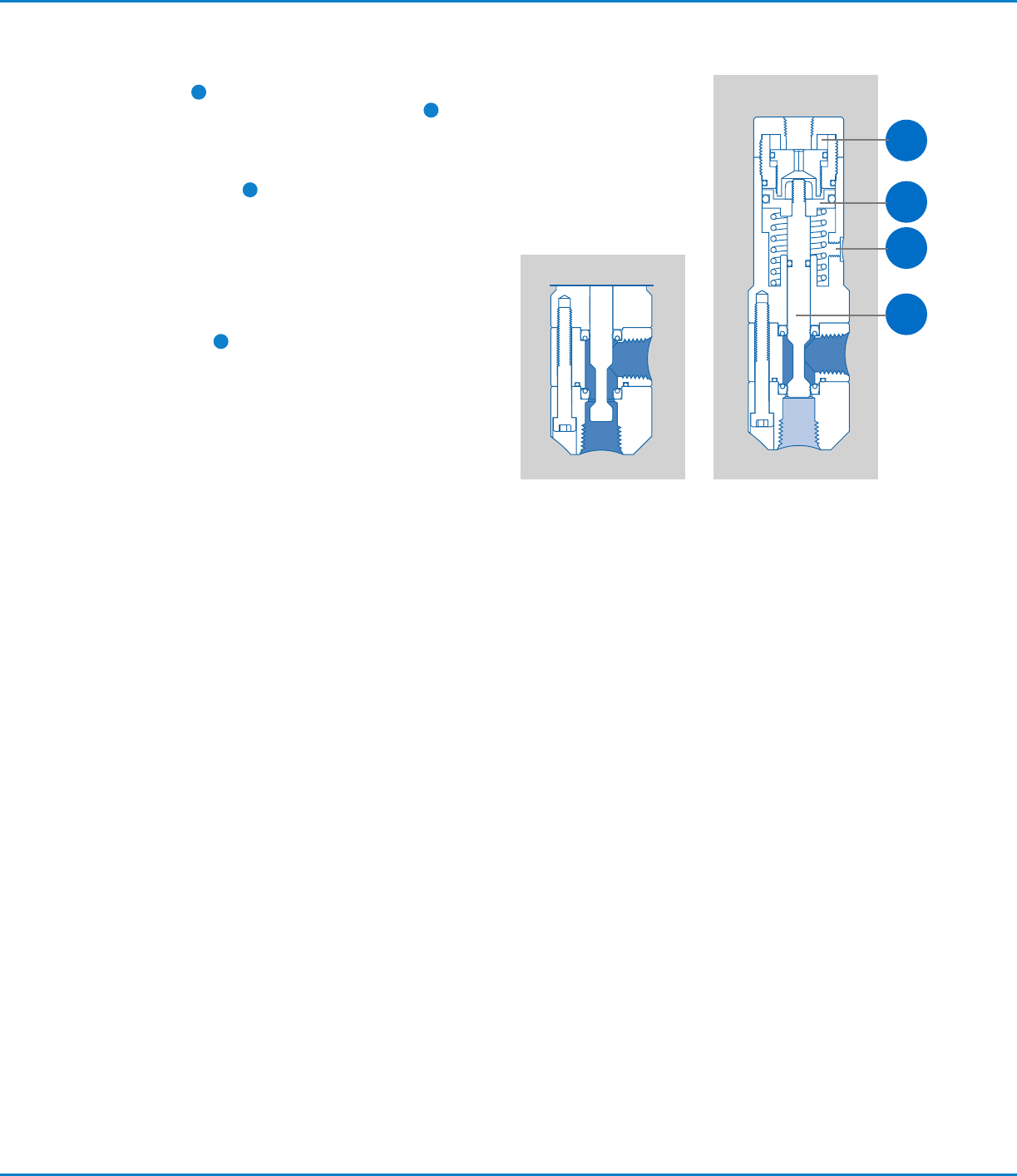
How the Valve Operates
When air pressure at 4.8 bar (70 psi) is applied, the piston
shifts the shaft
1
to the open position, allowing fluid to flow.
At the end of the cycle, spring force on the piston
2
shifts
the shaft to the closed position, stopping fluid flow. During
the closing action, the 736HPA-NV valve provides snuff-back
of fluid for clean cutoff.
The stroke adjustment
3
can be used to regulate the
snuff-back to an amount appropriate for the fluid being
dispensed. Stroke adjustment can also be used to reduce
fluid surge when the valve opens to ensure consistent bead
widths and dot profiles. Refer to “Valve Stroke Adjustment”
below for instructions.
When dispensing very thick fluids at high cycle rates, the
double-acting feature ensures rapid closure. A double-
actuating air input
4
is provided on the side of the air
cylinder to allow double-acting operation using air pressure
to both open and close the valve.
The amount of fluid dispensed is determined by valve open-
time, fluid pressure, dispensing tip size, and fluid viscosity.
ClosedOpen
2
3
4
1
Valve Stroke Adjustment
The stroke is adjusted by moving the stroke limit stop. You
will need a 5/64" hex wrench to adjust the valve stroke.
1. To access the stop, first remove the air input hose from
the push-in air coupling by pushing down on the release
ring while pulling up on the tubing.
2. Insert a 5/64" hex wrench through the air coupling and
engage the stroke limit stop.
3. Adjust the stop toward or away from the piston to vary
the stroke:
• To decrease the amount of opening surge and closing
snuff-back, extend the limit stop by turning the wrench
clockwise.
• To increase the amount of surge and snuff-
back, retract the limit stop by turning the wrench
counterclockwise.
NOTE: Adjusting the stroke does not affect the flow rate.
4. Reinstall the air input hose by pushing the hose into the
coupling.
NOTE: For striping applications, fluid surge can be
reduced further by lowering the valve operating air
pressure down to, but not below, 2.7 bar (40 psi).
736HPA-NV | Operating Manual
5www.nordsonefd.com info@nordsonefd.com +1-401-431-7000 Sales and service of Nordson EFD dispensing systems are available worldwide.
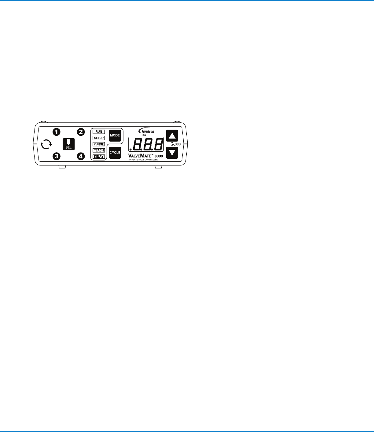
How the Valve is Controlled
The ValveMate
™
8000 provides easy adjustment of valve output for maximum end-user convenience and efficiency. Valve
open time is the primary control of deposit size. The 8000 puts push-button adjustment of valve open time where it needs to
be — at the valve.
The ValveMate 8000 features micro-processor circuity for extremely precise control of deposit size. Feed lines can be
purged, initial deposit sizes set, and adjustments made quickly and easily at the dispensing station, without stopping the
production line.
NOTE: For consistent dispense valve operation and easy adjustment of valve output, Nordson EFD recommends using the
ValveMate 8000 controller for all automatic, semi-automatic, and benchtop applications. Nordson EFD automated dispensing
systems integrate with ValveMate controllers for operating all pneumatic and BackPack
™
dispense valves.
Important Note: Order your 1-, 2-, 3- or 4-solenoid manifold
block assembly separately. Consult EFD for recommendations.
736HPA-NV | Operating Manual
6 www.nordsonefd.com info@nordsonefd.com +1-401-431-7000 Sales and service of Nordson EFD dispensing systems are available worldwide.
Specifications
NOTE: Specifications and technical details are subject to change without prior notification.
Item Specification
Size 134.4 mm length x 35.1 mm diameter (5.29" x 1.38")
Weight 544.0 g (19.2 oz)
Actuating air pressure required 4.8–6.2 bar (70–90 psi)
Maximum fluid pressure 172 bar (2500 psi)
Fluid inlet 1/4 NPT female
Fluid outlet 1/4 NPT female
Mounting 5/16-24 UNF tapped hole or adjustable mounting block
Cycle rate Exceeds 400 per minute
Air cylinder body 303 stainless steel
Fluid body 303 stainless steel
Outlet cap 303 stainless steel
Piston Hard-coated anodized aluminum
Spool (piston shaft) Hard-chrome coated stainless
Spool seals Polyester elastomer (Hytrel
®
) (Viton
®
optional)
Maximum operating temperature 43° C (110° F)
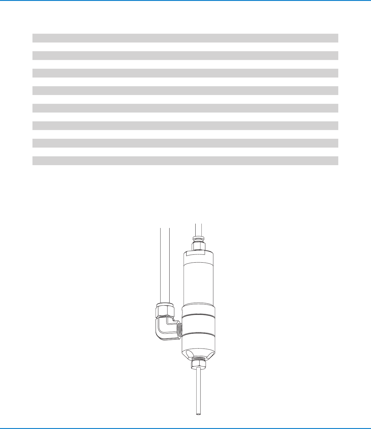
Operating Features
Control air hose
Air cylinder
body
Fluid supply
line
Fluid inlet
fitting
Dispensing tip